How LiDAR Optical Dome Works | Optical Geometry & Errors | Felix Glass
- Share
- publisher
- Felix Glass Co., Limited
- Issue Time
- Oct 26,2026
Summary
This article explains working principles of LiDAR optical domes. It covers ideal concentric spherical shell geometry, ray incidence condition, real‑world refraction, beam deviation, ghost reflection risk, critical geometric specifications and ray‑trace validation requirements for scanning LiDAR systems.
Felix Glass Knowledge Center
LiDAR & Sensing Guide
Understand how optical windows, domes, materials, and coatings influence the performance of LiDAR and optical sensing systems.
A sensor cover is part of the optical path. Its transmission, geometry, surface quality, and condition can affect the outgoing beam and the returning signal. Selecting it early helps engineers balance optical performance, environmental protection, and practical manufacturing requirements.
This guide introduces the decisions behind custom protective optics for laser ranging, robotic perception, industrial sensing, and outdoor monitoring.
Explore the Guide1. What Does This Guide Cover?
LiDAR stands for Light Detection and Ranging. It uses light to measure distance and, in many configurations, build a spatial representation of the surrounding scene. Optical sensing is broader: it also includes proximity detection, active infrared illumination, imaging, and other measurements based on received light.
This guide focuses on the protective optics in front of these systems. It explains how to define a cover that protects the sensor while preserving the useful beam and received signal. Detector electronics, complete sensor design, and system certification require separate assessment.
2. Explore the LiDAR & Sensing Topics
How LiDAR Optical Dome Works
Learn how curved protective optics interact with scanning beams, why the center of curvature matters, and where refraction or internal reflections can create errors.
Explore dome working principlesLiDAR Wavelength & Materials
Compare material-selection considerations for 905 nm, 940 nm, and 1550 nm sensing, including the importance of grade, thickness, and coating design.
Explore wavelength selectionOptical Dome Protection Principles
Understand how substrate, seals, mounting, contamination, and environmental tests work together to protect a sensor.
Explore protection principlesOptical Window & Dome Comparison
Compare flat and curved covers by field of view, optical alignment, manufacturability, and installation requirements.
Compare windows and domes3. How LiDAR Measures Distance
In pulsed time-of-flight LiDAR, a transmitter emits a light pulse and a receiver detects the reflected return. The system estimates range from the elapsed round-trip travel time:
Range = v × Δt / 2
Here, v is the speed of light in the propagation medium and Δt is the corrected round-trip time. For a simple estimate in air, v is approximately 3 × 10⁸ m/s. A 100 ns round trip corresponds to approximately 15 m.
This expression describes pulsed time-of-flight ranging, not every LiDAR architecture. Phase-based systems infer distance from modulation phase, while frequency-modulated continuous-wave systems use coherent detection and frequency information.
A protective cover introduces additional optical path and potential reflections. Its contribution should be included in optical analysis and system calibration, particularly when the scan angle or temperature changes.
4. Where Protective Optics Fit in the System
A typical optical path includes a laser source, beam-forming optics, optional scanning elements, an external cover, the target, receiver optics, spectral filtering, and a detector. Some designs share one cover between transmitter and receiver; others use separate apertures.
The cover must transmit the useful signal across the operating aperture and angular range. Reflections from its surfaces can also return toward the transmitter or couple directly into the receiver, producing unwanted signals that may be especially troublesome at short range.
Define transmitter and receiver footprints separately. A cover that clears the outgoing beam can still clip part of the receiver field of view.
5. How a LiDAR Optical Dome Works
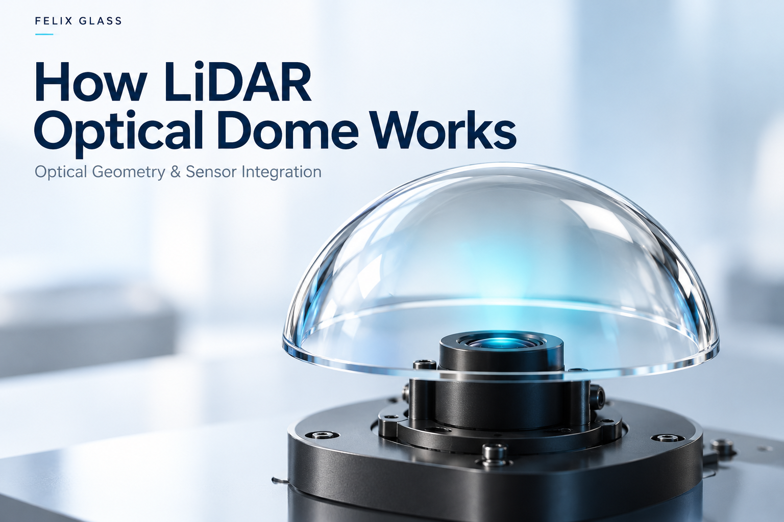
A dome provides a curved protective boundary around an optical system. For an ideal concentric spherical shell, a ray passing through the common center of curvature meets both surfaces at normal incidence. This geometric condition can reduce angular refraction for those rays.
A real scanning system contains finite beam footprints and a receiver aperture. The scan origin, entrance pupil, and dome center may not coincide. Off-center rays can experience refraction, optical path variation, and aberrations, so a dome is not automatically distortion-free.
- Geometry: Specify inner and outer radii, wall thickness, overall height, and clear aperture.
- Alignment: Define the relationship between optical surfaces, flange or mounting datum, and sensor position.
- Angular performance: Evaluate both transmission and beam deviation across the full scan.
- Validation: Trace the actual transmitter and receiver ray bundles through the cover.
A dome is a useful candidate for a wide scanning field, but the final choice depends on the complete sensor layout.
6. LiDAR Wavelengths and Sensing Requirements
| Wavelength | Design context | Cover selection questions |
|---|---|---|
| 905 nm | Used in pulsed near-infrared laser ranging and LiDAR. | Does transmission meet the requirement across the laser spectrum, temperature shift, and scan angles? |
| 940 nm | Used in active infrared sensing, proximity detection, and time-of-flight depth sensing. | Does the cover support the illumination and receiver channels, including any cosmetic masking? |
| 1550 nm | Used in some pulsed and coherent LiDAR systems. | Are substrate absorption, coating behavior, and polarization effects acceptable at the actual thickness? |
Choose the wavelength together with the emitter, detector, target characteristics, atmospheric conditions, and safety requirements. A cover that appears transparent in visible light does not establish its transmission at the sensing wavelength.
A 1550 nm wavelength does not by itself make a product eye-safe. Laser safety depends on accessible emission, operating conditions, and the applicable product assessment.
7. Selecting the Optical Material
Start with measured transmission for the specified grade and thickness, then evaluate environmental and manufacturing constraints. The following are screening considerations, not interchangeable material approvals.
| Material | Why evaluate it? | What needs confirmation? |
|---|---|---|
| BK7 / H-K9L optical glass | Candidate for many visible and near-infrared protective optics. | Actual supplier grade, spectral transmission, thermal behavior, and equivalence requirements; substitutions need approval. |
| Fused silica | Candidate where optical quality and low thermal expansion matter. | Grade-dependent absorption, especially for infrared use; do not specify all fused silica grades as equivalent. |
| Sapphire | Candidate where surface hardness and abrasion resistance are priorities. | Crystal orientation, birefringence, coating design, cost, and edge or mounting stresses; hardness does not mean impact-proof. |
| Optical-grade PC / PMMA | Candidate for lightweight or molded covers. | Grade-specific spectral absorption, molding stress, temperature stability, weathering, and surface protection. |
| Silicon for selected SWIR designs | Potential candidate at 1550 nm when visible transparency is unnecessary. | Absorption and resistivity of the specified grade, high-index reflection, and AR coating. It is not a suitable transmissive cover at 905 or 940 nm. |
For coated parts, request finished-component transmission as well as the substrate data. A bulk-material curve alone does not describe the assembled optical performance.
8. AR Coatings, Filters, and Signal Throughput
Anti-reflection coatings reduce surface reflection over a defined wavelength and incidence-angle range. A coating optimized at normal incidence may behave differently at the edge of a wide scan, including different responses for s- and p-polarized light.
Specify the wavelength band, incidence-angle range, polarization, coated surfaces, and whether transmission is a minimum or an average. Define whether the requirement applies to the complete component or an individual surface.
If outgoing and returning light each pass once through a cover with single-pass transmission T, its simplified contribution to round-trip throughput is T². For example, 95% per pass gives approximately 90.25% for the two passages. This is an illustrative transmission calculation, not a prediction of detection range.
AR treatment and spectral filtering serve different functions. A narrowband receiver filter can reject unwanted background light; an AR-coated cover alone does not provide equivalent out-of-band blocking.
9. Optical Dome Protection Principles
Environmental protection comes from the complete assembly: cover geometry, material, coating, seal, housing, and mounting method. A bare dome has no independent housing ingress-protection rating.
- Rain and contamination: Water droplets, dust, fingerprints, and deposits can scatter light or obstruct part of the field.
- Cleaning and wear: Evaluate abrasion resistance and the effects of the intended cleaning chemicals and procedures.
- Thermal loading: Consider differential expansion between the cover and housing, mounting compliance, and thermal cycling.
- Impact and vibration: Test the mounted component under defined loads and inspect both mechanical and optical changes.
- Pressure: Determine thickness from geometry, support, material data, load cases, and an appropriate safety margin; confirm by analysis and testing.
Hydrophobic or other surface treatments may support contamination management, but their optical compatibility and durability must be verified. They do not guarantee a permanently clear or maintenance-free surface.
10. Optical Window & Dome Comparison
| Consideration | Flat optical window | Optical dome |
|---|---|---|
| Field of view | Often practical for forward-looking systems; large scan angles increase incidence angle. | Can accommodate broad angular coverage when geometry and sensor position are coordinated. |
| Beam behavior | An ideal parallel plate in the same medium on both sides preserves the emerging ray direction but causes lateral displacement at oblique incidence. | Behavior depends strongly on radii, concentricity, alignment, and ray position. |
| Imaging effects | Can affect focus and aberrations in converging or diverging beams. | Can introduce aberrations and field-dependent errors for off-center ray bundles. |
| Mounting | Often compatible with simpler planar sealing surfaces. | Requires clear flange, edge, and optical-center datums. |
| Production and inspection | Planar geometry often simplifies metrology. | Curved-surface measurement and wall-thickness control can be more demanding. |
Begin with the required optical field and housing envelope. Compare both geometries with the same ray model, environmental loads, and acceptance criteria before choosing.
11. Specifications That Matter
- Optical aperture: Define the useful region and permissible edge exclusion.
- Surface and transmitted wavefront: Identify the measurement wavelength, aperture, and relevant surface or system quantity.
- Beam deviation: Set allowable steering or angular error across the operational field.
- Surface quality: State the inspection standard and acceptance level; scratch-dig notation alone does not define every inspection condition.
- Window geometry: Define thickness, wedge or parallelism, outline, and mounting features.
- Dome geometry: Define radii, thickness variation, concentricity, height, flange, and datums.
- Coating performance: State spectral and angular conditions, durability requirements, and test methods.
Keep cosmetic appearance separate from optical acceptance. A visually clear surface can still produce unacceptable beam deviation, while a cosmetic imperfection outside the clear aperture may have no optical consequence.
12. Prototype and Validate the Complete Optical Path
- Establish baseline sensor performance without the proposed cover under controlled conditions.
- Measure covered-system performance across scan angle, distance, target reflectivity, and background illumination.
- Check short-range crosstalk, ghost returns, range bias, and signal strength.
- Repeat relevant measurements over operating temperature and after defined environmental exposures.
- Evaluate cleaning, contamination, assembly repeatability, and replacement-part consistency.
- Freeze the approved drawing, coating specification, inspection methods, and change-control process.
Calibration can compensate for some repeatable effects, but it should not substitute for adequate transmission, stable geometry, or control of unwanted reflections.
13. What to Include in a Custom Optics RFQ
Provide a 2D drawing and, where helpful, a 3D model together with these application details:
- Sensor type, wavelength range, laser operating mode, and polarization requirements.
- Transmitter and receiver locations, beam footprints, scan angles, and clear apertures.
- Material and acceptable alternatives, dimensions, tolerances, and mounting datums.
- Finished-part transmission, beam deviation or wavefront limits, and surface quality.
- Coated surfaces, angular range, and environmental or cleaning requirements.
- Prototype quantity, expected production demand, delivery target, and inspection documentation.
If some requirements are still open, identify them explicitly. A preliminary optical layout and operating environment can be more useful than a tightly toleranced drawing with an undefined optical path.
14. Frequently Asked Questions
Does every LiDAR system need an optical dome?
No. Flat windows, domes, and other cover geometries can all be appropriate. Select the geometry from field of view, sensor placement, housing design, and optical performance.
Can one cover work at both 905 nm and 1550 nm?
Potentially. The substrate and coating must meet both spectral requirements at the specified thickness and angles. Do not assume that a single-wavelength coating provides adequate performance at the other wavelength.
Is sapphire always the best material?
No. Its hardness may be valuable, but crystal orientation, optical behavior, manufacturing cost, and mounting conditions still matter. Other materials can better fit a particular design.
Will a dome increase LiDAR range?
A dome primarily provides a protective optical boundary. Its transmission, scatter, and reflections affect the signal budget, but it cannot independently guarantee a range increase.
Can an AR coating eliminate all internal reflections?
No. AR coatings reduce reflection within their design conditions. Residual reflections, geometry, receiver placement, and stray-light control must still be evaluated.
Can the same design be used underwater?
Not without reassessment. The surrounding refractive index, propagation losses, sealing, and pressure loads change. An air-use optical design and calibration cannot simply be assumed valid underwater.
What should be checked before volume production?
Approve representative prototypes in the sensor assembly, verify the agreed environmental and optical tests, and establish production inspection and change-control requirements.
15. Discuss Your LiDAR Window or Dome Requirements
Felix Glass focuses on custom precision optical components. Share your application, drawing, wavelength, scan range, and target quantities to begin a manufacturability and specification review for a custom optical window or dome.
Material selection, achievable tolerances, coating performance, inspection scope, and lead time should be confirmed for the individual project before ordering.
Dongguan Felix Glass Co., Ltd.
Email: james@felixglass.com