IR Transmission Range Guide (8–15 µm)
- Share
- publisher
- Felix Glass Co., Limited
- Issue Time
- Oct 24,2026
Summary
This guide explains LWIR 8‑12, 8‑14 and 8‑15 µm infrared bands. It covers material thickness effect, coating limits, detector cutoff, atmospheric absorption, throughput calculation, average/minimum transmission and specification workflow for infrared windows and lenses.
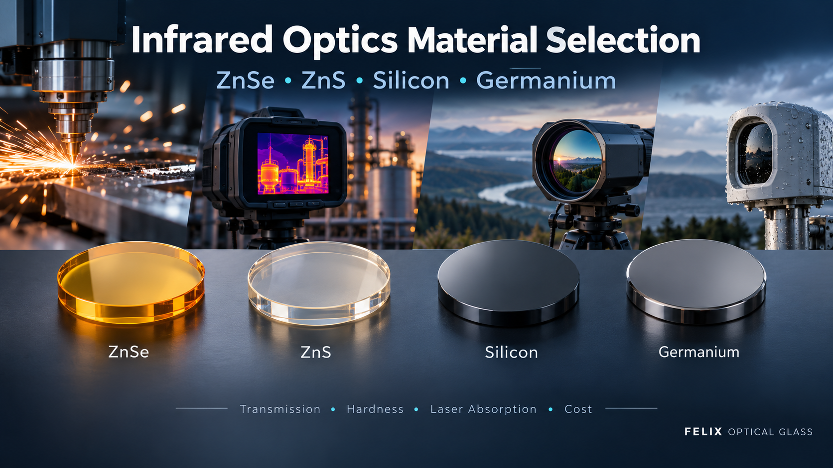
An infrared transmission range identifies wavelengths that can pass through a material or optical component under stated conditions. It does not, by itself, specify how much radiation reaches a detector or how well a camera performs. This guide examines the 8–15 µm region, including the commonly specified 8–12 µm and 8–14 µm bands. It explains how to turn a broad wavelength label into a useful specification for an infrared window, lens, dome or filter. The notation describes a wavelength interval from 8 to 15 micrometers, equivalent to 8,000–15,000 nanometers. It does not state a transmission threshold, material thickness, operating temperature or coating design. A component that passes a small fraction of radiation at 15 µm can technically show transmission there while remaining unsuitable for a high-throughput application. “Transmits to 15 µm” is therefore not equivalent to “high transmission from 8 to 15 µm.” The term LWIR is useful for broad classification, but its boundaries vary with convention. Use numerical wavelengths for design, quotation and inspection. A wider band can collect more useful signal when the source, optics and detector support it. It can also introduce additional background, absorption, aberration or coating complexity. Bandwidth should follow the measurement or imaging task rather than a preference for the largest number. For example, extending a window specification to 15 µm offers little benefit to a camera whose response is negligible above 13.5 µm. Objects above absolute zero emit thermal radiation. For an ideal blackbody, the peak of the wavelength-based spectrum follows Wien's displacement law: λmax ≈ 2898/T, with wavelength in micrometers and temperature in kelvin. At 300 K, approximately 27°C, the peak occurs near 9.7 µm. This helps explain why long-wave infrared cameras are useful for observing objects near room temperature. The peak is not a narrow emission line. Radiation extends across a broad spectrum, and the detected contribution from each wavelength depends on the object, its emissivity, the atmosphere and the instrument. A warmer object shifts the peak toward shorter wavelengths, but can still produce a useful LWIR signal. An atmospheric window is a region of relatively low atmospheric absorption. It is not a guarantee of uniform transmission, and its useful boundaries depend on the path and conditions. Water vapor, ozone and carbon dioxide introduce wavelength-dependent absorption. Ozone has a feature near 9.6–9.7 µm, while carbon dioxide has a strong band around 15 µm [1, 2]. Their impact depends on gas concentration, path length and observing geometry. This is especially relevant when extending a requirement from 14 to 15 µm. Good transmission through a laboratory optic does not remove absorption in the air between the target and camera. Short indoor paths, long horizontal outdoor paths and satellite viewing paths are different cases. Use a suitable atmospheric model or measured data for the intended environment; a generic atmospheric plot should not be treated as a predicted field result. The overlap of nominal bands is a useful initial screen, but the actual spectral curves are more informative. A narrow absorption dip or a gradual detector cutoff may significantly affect a task even when every datasheet lists the same nominal endpoints. Crystran lists a broad nominal range of 0.6–21 µm for ZnSe [3]. This makes it worth evaluating for an extended band, but does not establish a finished-window guarantee. Likewise, a supplier's ZnS range approaching 14 µm does not establish a high-transmission 15 µm design [4]. Silicon illustrates the danger of using endpoints alone. Crystran lists a broad range but also describes its common use in the 3–5 µm band [5]. Its grade-specific spectral structure must be examined before considering a broad LWIR application. For a homogeneous material, a simplified internal-transmission model is: τinternal(λ) = exp[−α(λ)t] Here α(λ) is the wavelength-dependent absorption coefficient and t is path length in compatible units. The expression excludes surface reflection, coating loss and scattering. As a hypothetical example, at a wavelength where α = 0.20 cm−1, a 2 mm path gives approximately 96.1% internal transmission and a 5 mm path gives approximately 90.5%. Neither number is complete-part transmission. Near a material's absorption edge, additional thickness can have a stronger effect because α rises. At oblique incidence, the path through the substrate is also longer. Obtain data for the intended thickness and angles rather than applying a thin-sample curve directly. Thickness must still satisfy mechanical needs. Optimize optical throughput and structural performance together. An AR or broadband AR coating reduces reflection over a designed band. “BBAR” does not mean that the coating performs equally well at every infrared wavelength. Specify the band, allowable reflectance or transmission, angle range and relevant polarization conditions. An 8–12 µm coating should not be accepted for an 8–15 µm requirement without additional evidence. Protective DLC or hard-carbon layers also affect the spectral response. Review the complete external and internal coating stacks, including absorption and environmental requirements. A coating cannot restore radiation already absorbed inside the substrate. A normal-incidence witness-coupon result may not represent a curved dome or an oblique field ray. Match the verification method to the optical geometry and define when finished-part testing is required. The optical substrate is not always the limiting component. A detector's sensing layer, package window and internal filters may define the effective cut-on and cutoff wavelengths. FLIR describes one standard microbolometer package in which the front window sets a 7.5 µm short-wavelength cut-on and the detector sets a 13.5 µm long-wavelength cutoff [6]. This is a specific example, not a universal microbolometer range. Request the spectral responsivity of the actual detector configuration. A nominal range should be accompanied by its definition where endpoint behavior matters. If the detector has no useful response at 15 µm, extending the external window alone will not create a 15 µm camera. Conversely, a detector capable of that wavelength still requires compatible optics and an appropriate signal model. For a simplified optical path, neglecting multiple-reflection coupling: τoptics(λ) ≈ τwindow(λ) × τlens(λ) × τfilter(λ) Use fractional transmission values at the same wavelength. For example, 0.90 × 0.92 × 0.85 = 0.704, or approximately 70.4%. This single-wavelength example does not define a broadband result. A simplified target-signal calculation is: S ∝ ∫ Ltarget(λ) τatmosphere(λ) τoptics(λ) Rdetector(λ) dλ R is detector responsivity defined consistently with the radiance units. The expression omits geometry and additive radiation from the atmosphere, optics and reflected surroundings. These may be necessary for a radiometric model. Do not normally multiply unrelated broadband averages. Two components with the same average transmission can have different spectral shapes and therefore different combined performance. A band-average requirement controls the mean over a stated interval. A minimum requirement controls the lowest permitted transmission within that interval. Neither automatically implies the other. Consider a hypothetical window with 95% transmission from 8 to 12 µm and 60% from 12 to 15 µm. Its uniformly wavelength-weighted average over 8–15 µm is: (4 × 95% + 3 × 60%)/7 = 80% The same window has a 95% average over 8–12 µm. Changing the averaging interval changes the result even though the physical component is unchanged. Define whether averaging is uniform in wavelength, uniform in wavenumber, or weighted by a source and detector response. These methods generally produce different values. When a spectral dip would compromise the application, specify both a band average and a minimum, plus suitable measurement resolution. Set achievable limits after material and coating review. Fourier-transform infrared spectroscopy can characterize transmission across this region. A useful report identifies the sample and the test conditions, not just a smooth curve. Wavelength and wavenumber are related by λ (µm) = 10,000 / wavenumber (cm−1). Thus, 8 µm corresponds to 1250 cm−1 and 15 µm to about 667 cm−1. Axis direction and sample spacing change under this conversion. Residual atmospheric absorption can appear when sample and background conditions differ. Investigate unexpected features instead of automatically attributing them to the substrate. Instrument resolution and detector coverage must also be adequate for the specified endpoints. Example specification wording: “Finished coated window transmission shall be measured from 8.0 to 15.0 µm at the agreed incidence angle and temperature. Report the uniformly wavelength-weighted band average, minimum transmission and full measured spectrum. Acceptance limits, spectral resolution and measurement uncertainty shall be agreed before manufacture.” This wording defines the reporting approach; it still needs numerical performance limits and mechanical specifications. An isolated requirement such as “T > 95% at 8–15 µm” leaves too much ambiguity for production acceptance. No. The extra interval can introduce different material, coating, detector and atmospheric limitations. Qualify the requested band explicitly. No. Atmospheric absorption varies with wavelength and conditions. The strong carbon-dioxide band near 15 µm is especially relevant to the extended long-wavelength end. No. Added bandwidth helps only when it contributes useful signal relative to noise and background and is supported by the detector and optical design. Only after its performance across the extended interval is verified. A coating name or a plot outside the guaranteed band is not sufficient evidence. No. Review the actual grade, thickness and complete-part spectrum near the long-wavelength absorption edge. A nominal LWIR classification does not establish an 8–15 µm guarantee. Their spectral shapes may differ. The detector, source and atmosphere weight different wavelengths unequally, so equal unweighted averages need not yield equal useful signals. No. Temperature measurement also depends on emissivity, reflected radiation, calibration, atmospheric conditions and window emission. Validate the final system. When geometry, thickness, coating uniformity or acceptance requirements make it necessary, yes. Witness samples can support process control but do not automatically represent every feature of a finished component. For a custom infrared window, lens or dome, share the exact wavelength interval together with the detector information, dimensions, coating requirements and operating environment. These details help establish a specification that can be manufactured and verified. Felix Glass focuses on custom precision optical components. Material and coating proposals should be reviewed against the finished-part requirements, with feasibility and inspection criteria confirmed before production. Send your drawing, required spectral performance, prototype and production quantities, and any available detector-response or reference-transmission data. Discuss Your Infrared Requirements Email: james@felixglass.com Other articles in this series: Infrared Imaging Principles; Germanium (Ge) Lens Guide; ZnS Infrared Window Explained; Infrared Optical Material Comparison. Numerical examples are explanatory calculations, not measured product performance. Use traceable spectral data and agreed test conditions for acceptance.IR Transmission Range Guide (8–15 µm)
1. What Does “8–15 µm Transmission” Mean?
2. Comparing 8–12, 8–14 and 8–15 µm
Specified band Practical meaning What needs attention 8–12 µm A common thermal-infrared optical design interval Performance inside this band does not qualify the component above 12 µm 8–14 µm A broader interval used in many thermal-imaging discussions Check material absorption, coating response and detector sensitivity toward 14 µm 8–15 µm An explicitly extended interval requiring its own qualification Verify the 14–15 µm region and atmospheric effects rather than assuming standard LWIR compatibility 3. Why This Region Matters for Thermal Imaging
4. The Atmospheric Window Is Not Perfectly Transparent
5. Four Different Ranges Must Be Kept Separate
Range or response What it describes Typical limitation Material transmission Bulk and sometimes surface behavior of a specified sample Grade, thickness, temperature and absorption features Coating passband Performance of a coating stack over a defined interval Band edges, incidence angle and polarization Detector response Electrical response to incident radiation Sensing material, package window and filters Complete system response Combined wavelength-dependent sensitivity All optical elements, detector response and the external path 6. Material Selection Across 8–15 µm
Material Role in the review Key qualification issue ZnSe A candidate for broad infrared transmission Finished-thickness absorption, coating performance and mechanical requirements ZnS A candidate for infrared protective and multispectral windows Grade and long-wavelength transmission; do not assume high throughput through 15 µm Germanium A reference material used in thermal-infrared optics Temperature, thickness, interface losses and the actual qualified upper wavelength Silicon A grade-dependent case requiring detailed spectral review Absorption bands, impurities, resistivity and thickness Chalcogenide glass A family of composition-specific infrared materials Exact glass type, absorption edge and validated optical model Ordinary optical glass, fused silica and sapphire Not standard choices for full-band 8–15 µm transmissive windows Mechanical advantages cannot compensate for unsuitable spectral transmission 7. How Thickness Changes Transmission
8. AR, BBAR and DLC Coatings Have Their Own Limits
9. Detector and Package Windows Can Set the Band Edges
10. Calculate Throughput Wavelength by Wavelength
11. Average Transmission vs Minimum Transmission
12. How to Read and Verify an FTIR Transmission Report
13. A Practical 8–15 µm Specification Workflow
14. Frequently Asked Questions
Are 8–14 µm and 8–15 µm interchangeable?
Is 8–15 µm a uniformly transparent atmospheric window?
Does broader transmission always produce a better image?
Can an 8–12 µm AR coating be used for 8–15 µm?
Can ZnS be assumed to cover 15 µm?
Why can two windows with the same average transmission perform differently?
Does a good transmission curve guarantee accurate thermography?
Should transmission be measured on the actual component?
15. Define Your Infrared Band with Felix Glass
Request an Infrared Transmission Review
Dongguan Felix Glass Co., Ltd.Continue Reading
Technical References