Infrared Dome vs Flat Window: Choose the Right Optic for Your System
- Share
- publisher
- Felix Glass Co., Limited
- Issue Time
- Oct 20,2026
Summary
Learn to choose between infrared domes and flat windows by evaluating optical layout, mounting, coating and system-level performance for your infrared sensor application.
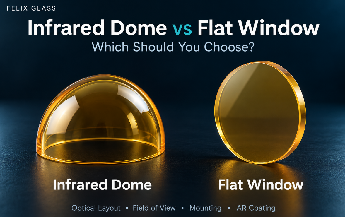
Infrared Dome vs Flat Window: Which Should You Choose?
When designing an infrared sensor enclosure, one early decision is whether to use a curved dome or a flat protective window.
Both can separate the optical assembly from its surroundings. However, their geometry creates different requirements for optical design, mounting, coating and inspection.
The right choice depends on how light passes through the protective optic and how the complete assembly will operate. A dome is not automatically better for every wide-angle system, and a flat window is not always the most economical choice once system integration is considered.
Start with the Optical Layout
Before comparing shapes, define the sensor’s field of view, entrance-pupil location, available installation space and required clear aperture.
These details help establish whether the protective optic blocks any useful rays and what angles those rays make with its surfaces.
For a dome, the relationship between the center of curvature and the optical system is especially important. A curved surface alone does not guarantee favorable ray angles.
For a flat window, the designer should evaluate the rays across the complete field rather than checking only the central optical axis.
A Practical Comparison
| Design consideration | Infrared dome | Flat infrared window |
|---|---|---|
| Geometry | Curved shell with defined inner and outer surfaces | Planar component with defined thickness |
| Optical integration | Requires review of curvature, position and wall geometry | Requires review of thickness, tilt and ray angles |
| Clear aperture | Defined over the useful curved region | Defined over the useful planar region |
| Mounting | Usually requires a rim, flange or shaped seating interface | Often uses a planar seating interface |
| Coating specification | Must account for ray angles across the curved surfaces | Must account for the system’s incidence-angle range |
| Inspection | May require specialized curved-component arrangements | Often accommodates more conventional planar inspection |
| Selection basis | Complete optical and mechanical design | Complete optical and mechanical design |
This comparison provides a starting point. Final suitability should be assessed against the actual system requirements.
When Is a Dome Worth Evaluating?
A dome is worth considering when the protective surface must accommodate a broad viewing region, a moving optical assembly or a curved external envelope.
The optical designer should examine the dome together with the sensor or lens assembly. Important questions include:
- Where is the entrance pupil relative to the dome?
- What incidence angles occur across the field?
- Does the rim obstruct any useful rays?
- How do the inner and outer surfaces affect image quality?
- What manufacturing tolerances can the optical design accept?
For a scanning or moving system, check the full range of operating positions. A clear view in the central position does not establish clearance throughout the movement.
When Is a Flat Window Worth Evaluating?
A flat window is often a practical starting point for systems with a suitable planar enclosure interface.
It can simplify some aspects of mechanical integration, particularly where the housing already provides a flat mounting surface. However, optical performance still needs review.
The design should consider the window’s location, thickness, tilt and the angles encountered by rays at the edge of the field.
A flat window should therefore be included in the optical model where its effect could influence system performance. Selecting a material that transmits the required band is only one part of that assessment.
Compare Optical Performance at System Level
Neither shape should be selected from appearance alone.
A useful comparison evaluates both options against the same requirements, such as:
- Usable field of view.
- Image quality across the field.
- Permitted optical-path distortion.
- Stray-light and reflection behavior.
- Required spectral transmission.
- Available installation space.
For demanding imaging systems, ask the optical designer to include the protective component in the system model before finalizing the production drawing.
This can reveal whether changes to curvature, thickness, position or mounting geometry are needed before samples are manufactured.
Keep Material Selection Separate from Shape Selection
Choosing a dome does not determine the material, and choosing a flat window does not remove the need for material evaluation.
For either geometry, define the operating wavelengths, transmission targets, exposure conditions and material grade.
If alternative materials are acceptable, ask suppliers to assess them against the same performance requirements. Avoid comparing one quotation based on a defined material grade with another based only on a general material name.
The finished component’s performance depends on the substrate, geometry, surface finish and coating working together.
Specify Coatings for the Actual Ray Angles
A coating described only as “broadband AR” leaves important details unresolved.
For both domes and flat windows, provide the required wavelength bands and the relevant incidence-angle range. Include polarization requirements where they matter.
On a dome, surface curvature changes the local surface normal. On a flat window, off-axis rays may still encounter substantial incidence angles. In both cases, the coating specification should follow the optical layout.
Also identify which surfaces require coating and which mounting or bonding regions must remain uncoated.
Review the Mounting Interface Early
A protective optic should be assessed together with its housing.
For a dome, the rim or flange may need particular attention because it locates the component and transfers mounting loads. For a flat window, the seating surface, retaining arrangement and edge clearance also need definition.
Provide a housing section drawing showing:
| Interface detail | Information to define |
|---|---|
| Seating surface | Contact location and geometry |
| Retention | Retaining ring, clamp or other arrangement |
| Sealing | Seal location and applicable requirements |
| Clearance | Space between the optic and housing |
| Bonding | Adhesive area, if applicable |
| Coating exclusions | Areas that must remain uncoated |
If the assembly operates under a pressure differential, assess the complete component and mounting arrangement. Shape alone does not establish a pressure rating.
Compare Total Project Cost
A quotation should be evaluated against the same scope.
Compare material, optical tolerances, coating, inspection, tooling, prototype quantity and required documentation. Include any differences in the housing or assembly work.
A lower component price may not produce the lowest total project cost if additional integration work is needed.
Similarly, a more complex protective optic may be justified if the complete system benefits from its geometry. That decision should follow the engineering assessment rather than a general assumption about either shape.
Use Prototypes to Confirm the Decision
When both options remain feasible, prototype testing can resolve the uncertainties that matter most.
Define the evaluation plan before ordering. Depending on the project, it may cover mechanical fit, spectral transmission, image quality, assembly compatibility or environmental performance.
Record the drawing revision, coating specification and sample identification with the test results. Incorporate agreed changes into the production documents before repeat orders.
What to Send for a Feasibility Review
To compare an infrared dome with a flat window, provide:
- Application and operating wavelength band.
- Sensor field of view and available optical-layout information.
- Approximate envelope and clear-aperture requirements.
- Housing drawing or mounting concept.
- Preferred material and acceptable alternatives.
- Optical, coating and environmental requirements.
- Prototype and expected production quantities.
If the protective-optic geometry is still open, state that clearly in the enquiry. This allows the review to focus on feasible options before the design is fixed.
Discuss Your Infrared Protective Optic with Felix Glass
Send Felix Glass your available drawings, operating wavelengths and application requirements for a custom optical component enquiry.
If you are comparing a dome with a flat window, include the housing interface and optical-layout information so the proposed component can be reviewed in context.
Contact: James Fu
Company: FELIX OPTICAL GLASS
Email: james@felixglass.com
Website: https://www.felixglass.com/