Infrared Imaging Principles
- Share
- publisher
- Felix Glass Co., Limited
- Issue Time
- Oct 24,2026
Summary
This article explains infrared imaging basics, IR wavelength bands, thermal radiation rules, detector types, infrared optical material selection, AR coating and system performance factors, helping engineers select proper infrared optics components.
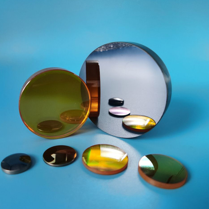
Infrared imaging converts invisible infrared radiation into an image that reveals differences in a scene. Depending on the wavelength band and application, those differences may come from reflected illumination, thermal emission or both. For engineers and equipment manufacturers, understanding these principles is the starting point for specifying infrared lenses, protective windows, domes and coatings. A detector can only use the radiation that the complete optical path delivers. An infrared imaging system collects radiation from a scene, forms an image on a compatible detector and converts the detector response into electronic image data. Infrared wavelengths lie beyond the red end of the visible spectrum. The term covers more than thermal cameras. Near-infrared and short-wave infrared systems commonly image reflected light, while mid-wave and long-wave infrared cameras are widely used to image thermal emission. Selecting a band therefore begins with a practical question: what physical difference must the camera detect? A bright pixel is not automatically a higher-temperature object. Its appearance depends on the selected palette, display scaling, surface properties, illumination and camera calibration. Band boundaries vary between conventions and detector technologies. Specify numerical wavelengths rather than relying only on “SWIR” or “LWIR.” A camera operating from 8 to 12 µm does not require exactly the same optical specification as one operating from 8 to 14 µm. SWIR can also detect thermal emission from sufficiently hot objects. The distinction between reflected-light imaging and thermal imaging depends on temperature and signal strength as well as wavelength. See technical reference [1]. Objects above absolute zero emit thermal radiation. For an ideal blackbody, Planck's law describes how spectral radiance varies with wavelength and temperature. Raising temperature increases emission and shifts the peak toward shorter wavelengths. Wien's displacement law gives the peak of the wavelength-based blackbody spectrum: λmax ≈ 2898 / T, where wavelength is in micrometers and temperature is in kelvin. At 300 K, approximately 27°C, the peak is about 9.7 µm. This helps explain the usefulness of LWIR for observing objects near room temperature. It does not mean that all their radiation occurs at 9.7 µm or that another band cannot detect them. Real surfaces depart from ideal blackbody behavior. Their spectral emissivity, surroundings and viewing geometry affect the radiation measured by a camera. Emissivity describes how strongly a surface emits relative to a blackbody at the same temperature and wavelength. It depends on material, finish, wavelength, angle and sometimes temperature. For an opaque surface, a simplified spectral model is: Lsurface = εLblackbody(T) + (1 − ε)Lbackground This model assumes an appropriate effective background radiance and omits atmosphere and intervening optics. Semitransparent targets require a transmitted-radiation term as well. A polished metal surface may reflect a warm person or nearby machinery, creating an apparent hot area. Accurate thermography therefore needs appropriate emissivity and reflected-background settings, together with compensation for the atmosphere and any protective window. Window temperature can also matter. See references [2] and [3]. The atmosphere does not transmit every infrared wavelength equally. Water vapor, carbon dioxide and other gases absorb selected wavelengths. The commonly used MWIR and LWIR bands overlap useful atmospheric transmission regions, but these regions are not perfectly transparent. Humidity, path length, rain, fog, aerosols and temperature conditions influence the available signal. Infrared imaging may improve visibility in some conditions, but “seeing through fog” is not a universal capability. For a short-range inspection station, component transmission and focus may dominate. For longer paths, atmospheric attenuation and target contrast become increasingly important. Choose the band against the intended environment and distance, not a generic transmission chart alone. Photon detectors generate an electrical response through interactions between incident photons and the detector material. InGaAs is common in SWIR systems. Other semiconductor detector technologies serve MWIR and LWIR applications; many high-performance thermal photon-detector systems require cooling. Uncooled microbolometers detect radiation through a small temperature-related change in the sensing element, typically read as a resistance change. They are widely used in LWIR cameras. The detector determines more than the spectral band. Pixel pitch, active area, acceptance angle and packaging constrain lens focal length, f-number, image circle and mechanical clearance. The optic and detector must be designed as a compatible system. A lens determines field of view, focus and the transfer of scene detail to the detector. For an ideal rectilinear system focused near infinity: Horizontal field of view ≈ 2 arctan(sensor width / (2 × focal length)) As an illustrative calculation, a 640-pixel-wide detector with 12 µm pixel pitch has a width of 7.68 mm. With a 25 mm focal-length lens, its horizontal field of view is approximately 17.5°. Actual distortion and usable image area can change the result. The f-number is focal length divided by entrance-pupil diameter. A lower f-number generally delivers more irradiance from an extended scene, subject to transmission, vignetting and detector acceptance. Thermal sensitivity specifications must be compared at stated optical conditions [4]. Resolution also depends on aberrations, diffraction, focus, sampling and modulation transfer function (MTF). For an ideal circular aperture, the Airy-pattern first-zero diameter is approximately 2.44λN. At 10 µm and f/1, it is about 24.4 µm; this is a diffraction scale, not a stand-alone camera resolution rating. A protective window or dome shields the camera from its environment while transmitting the required radiation. It remains part of the optical system even when it has no intended focusing function. Evaluate the complete assembly at its actual field angles and operating temperatures. A room-temperature transmission measurement alone does not demonstrate imaging performance or measurement accuracy. This is a selection overview, not a guaranteed transmission specification. Request data for the actual material grade, part thickness, coating and operating conditions. Material-family characteristics are discussed in reference [5]. Anti-reflection coatings reduce surface reflection within a specified spectral and angular range. High-index infrared substrates can lose substantial energy at uncoated interfaces, making coating design especially important. At normal incidence, an ideal lossless air-to-material interface has reflectance R = ((n − 1) / (n + 1))². A hypothetical refractive index of 2.4 gives approximately 17% reflection at one uncoated interface. This is an illustrative interface calculation, not a material datasheet or complete-window transmission value. For a first throughput budget, multiply component transmission values at the same wavelength: τsystem(λ) ≈ τwindow(λ) × τlens(λ) × τfilter(λ). Multiplying unrelated broadband averages can be misleading because the spectra may have different shapes. DLC or other protective coatings may improve environmental durability in suitable designs, but their compatibility and optical loss require evaluation. Specify each surface separately, including wavelength range, angle of incidence, polarization if relevant, and whether transmission is an average or a minimum requirement. Digital sharpening and contrast adjustment can improve visibility, but they cannot restore information that was lost through severe optical blur, absorption or inadequate sampling. Validate image quality with the final optics and enclosure. Provide the following information when requesting an engineering review or quotation: For example, a request for a protective window for an 8–12 µm camera should identify the window thickness, clear aperture, maximum ray angle, required band-average or minimum transmission and mounting environment. “High infrared transmission” alone is not a measurable acceptance criterion. No. Infrared imaging includes reflected-light methods such as many NIR and SWIR systems. Thermal imaging primarily uses emitted radiation to visualize scene differences. A passive thermal camera can operate without visible illumination because objects emit thermal radiation. Useful image contrast still depends on the scene, detector and optical system. Typical LWIR cameras cannot image a scene through ordinary window glass. They primarily detect radiation associated with the glass surface and reflections. Some NIR and SWIR systems can image through suitable glass within its transmission band. A conventional thermal camera does not see directly through a wall. It can reveal surface-temperature patterns that may result from conditions behind the wall, such as insulation differences or heat flow. No. Lower NETD indicates finer thermal sensitivity under comparable conditions. Absolute accuracy also depends on calibration, surface emissivity, reflected radiation, atmospheric effects and intervening optics. No. The better choice depends on target temperature, environment, detector technology, range, image requirements, size, power and cost. Band selection must follow the application. Do not assume so. The added window changes transmission and may contribute its own thermal emission. Radiometric systems may require window compensation and validation or recalibration in the final configuration. No. Usable system response depends on the detector, coating, material thickness, atmosphere and acceptance threshold. A nominal material range is not a guarantee of flat transmission or system sensitivity. Felix Glass focuses on custom precision optical components for integration into customer systems. For an infrared window, lens or dome project, share the operating band, drawing, environmental conditions and required quantities so the proposed material, coating and inspection requirements can be reviewed together. Component specifications should support the complete camera design. Transmission, imaging quality, durability and temperature-measurement performance are separate requirements and should be verified accordingly. Send your PDF drawing and STEP file, if available, together with your wavelength range and prototype or production quantities. Email: james@felixglass.com Related topics in this series: Germanium (Ge) Lens Guide; ZnS Infrared Window Explained; IR Transmission Range Guide (8–15 µm); Infrared Optical Material Comparison.Infrared Imaging Principles
1. What Is Infrared Imaging?
2. How an Infrared Image Is Formed
3. NIR, SWIR, MWIR and LWIR Explained
Band Typical working range Common signal source Example applications NIR Approximately 0.75–1.0 µm in many silicon-camera applications Reflected ambient or active illumination Machine vision, illuminated night imaging SWIR Often 0.9–1.7 µm with standard InGaAs detectors; extended systems cover other ranges Usually reflected light at ordinary scene temperatures Material sorting, moisture contrast, semiconductor inspection MWIR Commonly 3–5 µm Thermal emission, with possible reflected contributions Industrial process observation, hot-object imaging, specialized thermal systems LWIR Commonly 8–12 µm or approximately 8–14 µm Thermal emission, with reflected background contributions Building inspection, equipment monitoring, thermal observation 4. Why Objects Emit Infrared Radiation
5. Emissivity, Reflection and Temperature Measurement
6. Atmospheric Transmission and Working Distance
7. Detector Types and Their Optical Requirements
Photon detectors
Thermal detectors
8. How Infrared Lenses Control Image Quality
9. Why Protective Windows and Domes Matter
10. Optical Materials Must Match the Imaging Band
Material Relevant use Selection consideration Fused silica and suitable optical glasses NIR and selected SWIR applications Grade and absorption bands matter; ordinary visible optical glass is not a practical LWIR camera window. Sapphire Durable windows for suitable NIR, SWIR and portions of MWIR Check the long-wavelength absorption edge against thickness and temperature; not a standard 8–14 µm window. Silicon (Si) Selected SWIR and MWIR components Verify grade, absorption and coating; do not assume suitability across the full 8–14 µm band. Zinc selenide (ZnSe) Infrared lenses and windows, including thermal imaging Specify actual thickness, surface protection and coating performance. Zinc sulfide (ZnS) Infrared protective windows and imaging components Standard and multispectral grades differ; visible transmission and scatter requirements need explicit review. 11. AR Coatings, Protective Coatings and Throughput
12. What Determines Infrared Image Performance?
13. How to Specify an Infrared Optical Component
14. Frequently Asked Questions
Is infrared imaging the same as thermal imaging?
Can a thermal camera see in complete darkness?
Can a thermal camera see through ordinary glass?
Can thermal imaging see through walls?
Does a lower NETD mean better temperature accuracy?
Is MWIR always better than LWIR?
Can I add an infrared window without changing calibration?
Does an 8–15 µm material range guarantee an 8–15 µm imaging system?
15. Discuss Your Infrared Optics Requirements with Felix Glass
Request a Custom Infrared Optics Review
Dongguan Felix Glass Co., Ltd.Continue Reading in the Infrared Optics Guide
Technical References