Optical Coating Technology Comparison: AR, AG, AF, DLC & ITO
- Share
- publisher
- Felix Optical Glass Co., Limited
- Issue Time
- Oct 25,2026
Summary
Compare AR, AG, AF, DLC, reflective, filter and ITO coatings by function, then pick the right deposition route for windows, lenses, domes and mirrors. Learn key acceptance criteria. Get a quote.
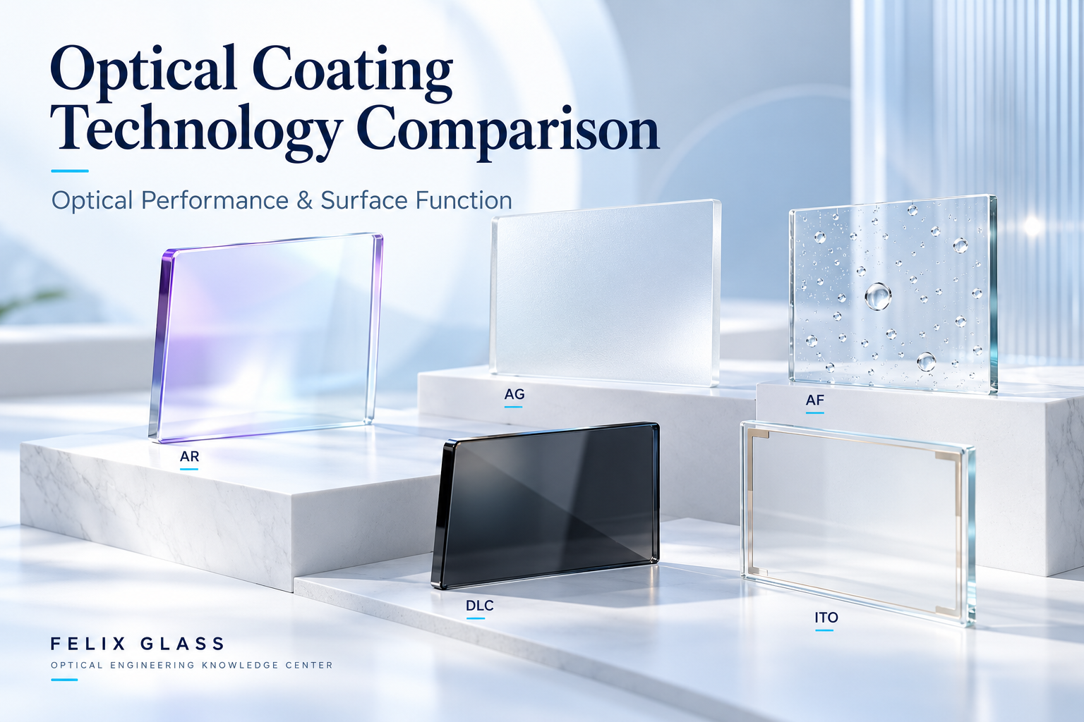
Knowledge Center · Optical Coating Guide Compare optical functions, surface protection, conductivity, and manufacturing routes for custom coated components. A useful comparison connects each technology to a measurable application requirement. This guide helps engineers and buyers distinguish coating functions from process names and choose a practical specification for windows, lenses, domes, mirrors, and display glass. Optical coating selection starts with the required result: transmit more light, soften glare, improve cleaning, reflect a beam, select wavelengths, resist exposure, or provide conductivity. AR and HR describe optical functions. DLC and ITO identify material families with useful functions. Evaporation and sputtering describe manufacturing processes. AG may be an etched texture rather than a deposited film. These terms should not be placed in a single ranking as if they were interchangeable products. This guide separates functional choices from manufacturing routes, then shows how to compare complete coated components under consistent conditions. This is a functional map, not a universal performance ranking. Specifications apply to a particular material, geometry, layer stack, and manufacturing route. Anti-reflection coatings use interference or an engineered index transition to reduce reflection. BBAR is a broadband AR design; a narrowband or V-coat concentrates performance near a specified wavelength. Choose a narrowband design for a sufficiently defined source when its spectral and angular tolerances can be met. Choose BBAR when a continuous wavelength range must be transmitted. A dual-band coating can address separated bands without guaranteeing the interval between them. Specify minimum component transmission separately from per-surface reflection when both matter. Substrate absorption and scatter are not captured by a low surface-reflection value. [1] AG changes light distribution through surface texture. AF changes the interaction between the surface and contaminants. A matte surface is not automatically easy to clean, and a cleanable surface is not necessarily matte. For displays, evaluate AG on the actual screen: haze alone does not establish clarity, black-level appearance, or sparkle. For AF, water contact angle alone does not establish resistance to oily fingerprints or cleaning performance. AG+AF can be a useful combination for touched control panels. Keep optical sensor apertures separately specified if texture-induced scatter would harm their function. Manufacturer AG and AF examples illustrate these distinct roles. [2] [3] Dielectric mirrors use interference in a layer stack. Metallic mirrors rely mainly on the optical response of a metal layer, often with protective or enhancing layers. Neither construction is always superior. Compare useful reflectance and loss under the actual operating conditions, not a peak catalog number measured elsewhere. A filter may transmit a selected band and reject others. A dichroic can direct different wavelength bands into different optical paths. Define both the desired transmission and the rejected spectrum. For blocking specified as optical density, OD = −log₁₀(T), with T expressed as a fraction. OD 3 corresponds to T = 0.001, or 0.1%, within the specified blocking band. This numerical relationship does not establish any particular product’s performance. Include transition width, edge or center wavelength, angle range, polarization, and measurement resolution. A filter specified at normal incidence can behave differently in a converging beam or at a tilted installation angle. A protective coating should improve resistance to defined exposure while preserving the optical function. Hardness alone does not establish adhesion, erosion resistance, chemical compatibility, or survival of repeated cleaning. Optical DLC is often considered for exposed infrared components. Its spectrum depends on composition, thickness, substrate, and any supporting layers. It should not be treated as a universal transparent hardcoat. Compare a DLC-based stack against BBAR using the same finished-part transmission and durability requirements. Manufacturer guidance notes that the two approaches can involve a tradeoff between protection and throughput. [4] For every protective treatment, specify performance after exposure as well as initial performance. Indium tin oxide can add conductivity to a transmitting component. Applications can include transparent electrodes, heaters, and electromagnetic attenuation structures, but each requires a complete electrical and optical design. Specify sheet resistance in Ω/□, its allowed variation, and the full transmission spectrum. Thickness, composition, and process influence both electrical and optical properties; visible transparency does not establish infrared transmission. For an ideal uniform rectangular film contacted by full-width electrodes on opposite edges, R = RₛL/W. For example, Rₛ = 100 Ω/□, electrode spacing L = 40 mm, and width W = 20 mm give R = 200 Ω, excluding contact resistance. This is a geometry example, not a heater design. Include busbars, contact resistance, current distribution, electrical isolation, and thermal limits where relevant. A sheet-resistance value alone does not guarantee heater uniformity or shielding effectiveness. Supplier ITO data illustrate the need to specify optical and electrical behavior together. [5] These are process families, not guaranteed quality levels. Published manufacturing guidance shows that multiple routes can meet demanding requirements, with application-dependent tradeoffs. [6] Do not specify IBS or any other route solely as a substitute for measurable acceptance criteria. Common combinations include AR+AF on a handled optical surface, AG+AF on a matte interface, and protective external coatings with BBAR on an internal infrared face. ITO can also be integrated with optical matching layers where the design permits. Every added layer can affect adhesion, reflection, absorption, stress, cleaning, or electrical access. The order and side assignment are part of the design. Do not assume that individually qualified coatings retain their original specifications after combination. These are screening choices. Final selection depends on the substrate, optical layout, exposure, production constraints, and validated acceptance limits. A fair comparison uses the same wavelength band, angle, polarization, aperture, temperature, substrate thickness, and measurement definition. Peak reflection, band-average transmission, haze, and sheet resistance are different quantities. Compare cost at the same specification and quantity. Tooling, masking, inspection, yield, qualification, and replacement can outweigh a difference in nominal coating price. Include prototype and production quantities, delivery target, and required reports. Where the process is not mandated, allow the supplier to propose a route that meets the agreed performance. A useful brief is: “Provide [function] on [substrate and faces], meeting [optical/electrical targets] under [conditions], with [durability acceptance], verified by [methods].” There is no universal best coating. Select the function, then compare qualified designs against the application requirements. BBAR is broadband anti-reflection: a type of AR design intended for a continuous wavelength band. Not automatically. AG redistributes light, while AR reduces reflection under specified conditions. Their effects on an imaging or display system differ. No. It can improve contamination behavior or cleaning, but marks and wear remain possible. No universal ranking applies. Compare the defined abrasion, chemical, adhesion, and environmental tests on the actual substrate. No. Process choice depends on materials, geometry, loss targets, stress, volume, and cost. Verify the delivered performance. It depends on the film and wavelength. Require measured spectral data rather than transferring a visible-transmission claim to an IR band. Often, but compatibility and finished-stack performance must be qualified. Additional layers can change optical, mechanical, or electrical behavior. Felix Glass supports custom optical components and functional glass projects. Share your drawing, substrate, required function, wavelength band, environment, and quantities for a project-specific review. Confirm the coating stack, treated faces, achievable performance, inspection scope, and production conditions before manufacture. Requests involving electrical contacts, complete assemblies, or system certification should define those responsibilities explicitly. Dongguan Felix Glass Co., Ltd.Optical Coating Technology Comparison
1. Compare Function Before Comparing Process
2. Coating and Surface-Treatment Comparison
Technology Primary purpose Key acceptance metrics Main limitation AR / BBAR Reduce surface reflection Spectral reflection and finished-part transmission at defined angles Limited to the qualified band, substrate, and optical conditions AG Redistribute reflected light to soften glare Gloss, haze, clarity, sparkle, and uniformity Scattering can affect image quality; not equivalent to low total reflection AF Improve fingerprint behavior or cleanability Contamination removal, wetting measurements, and retention after wear Does not make a surface permanently fingerprint-free HR dielectric coating Produce high reflection in a designed band Reflectance, absorption, scatter, angle, and polarization Bandwidth and angular requirements constrain the design Metallic mirror coating Provide reflection over a useful spectral range Reflectance spectrum, absorption, protection, and durability Metal choice and overcoat affect loss and environmental resistance Filter / dichroic coating Select or separate spectral bands Passband, blocking, edge position, angle, and polarization Spectrum can shift with operating conditions Optical DLC stack Combine surface protection with a defined optical response Transmission and durability on the specified substrate Durability and optical throughput may involve tradeoffs ITO conductive coating Add electrical conductivity Sheet resistance, optical spectrum, uniformity, and contact design Electrical and optical targets must be balanced 3. AR, BBAR, and Narrowband Designs
4. AG and AF Solve Different Surface Problems
5. Dielectric vs. Metallic Reflective Coatings
Consideration Dielectric mirror Metallic mirror Spectral design Can provide very high reflection in a designed band Often useful over broad ranges, depending on metal and overcoat Angle and polarization Must be included in the stack specification Still important; a broad spectrum does not mean angle independence Laser operation Evaluate absorption, damage qualification, and dispersion where relevant Evaluate absorbed power, thermal behavior, and damage qualification Environment Film adhesion, stress, and durability need qualification Oxidation or tarnishing and protective-layer performance may matter 6. Filters and Dichroics: More Than a Transmission Percentage
7. Protective Coatings and DLC
8. ITO: Conductivity with Optical Tradeoffs
9. Compare Manufacturing Routes Separately
Route Typical role Questions for qualification Thermal / electron-beam evaporation Deposits selected metals or dielectric films Material compatibility, density, stress, temperature, and environmental stability Ion-assisted deposition (IAD) Uses ion assistance during film growth Energy input, film properties, substrate compatibility, and repeatability Magnetron sputtering Deposits films from targets using a plasma process Uniformity, material control, stress, heat input, and production scale Ion-beam sputtering (IBS) Used for precision multilayer optics Loss, stability, stress, substrate size, cycle time, and cost Plasma / chemical deposition Used for selected films, including some carbon coatings Chemistry, adhesion, optical constants, process temperature, and durability Wet application / surface chemistry Used for selected functional layers Curing, uniformity, contamination, and compatibility with later steps Etching or texturing Creates AG through surface modification Texture distribution, optical effects, strength, and subsequent processing 10. Combining Functions in a Coating Stack
11. Application-Based Selection
Application Candidate function Main decision Imaging lens or precision window AR / BBAR Useful band, angles, reflection ghosts, and wavefront requirements Matte touchscreen or control panel AG+AF, with AR if needed Glare appearance, display clarity, cleaning, and touch experience Exposed IR window Qualified protective stack and IR AR Transmission after environmental exposure Laser steering mirror Dielectric or metallic reflection Band, incidence, absorbed power, damage testing, and pulse conditions Spectral sensing Filter or dichroic Passband and blocking across angle and temperature Heated or conductive window ITO or another qualified conductor Optical spectrum, resistance, contacts, and thermal uniformity 12. Compare Performance Under the Same Conditions
13. A Practical Selection and RFQ Workflow
14. Frequently Asked Questions
Which optical coating is best?
Is BBAR different from AR?
Can AG replace AR?
Does AF mean no fingerprints?
Is DLC always more durable than every other coating?
Is IBS always the best deposition method?
Can ITO remain transparent in infrared applications?
Can several functions be combined?
15. Discuss Your Custom Coated Component
Email: james@felixglass.com