Optical Dome Protection Principles
- Share
- publisher
- Felix Glass Co., Limited
- Issue Time
- Oct 26,2026
Summary
This article explains optical dome protection principles for LiDAR and optical sensors. Protection is performance of the full assembly including dome material, geometry, wall thickness, mounting, seals and coatings. It covers environmental threats, material screening, coating function limits, cleaning requirement and complete validation checklist for custom protective dome projects.
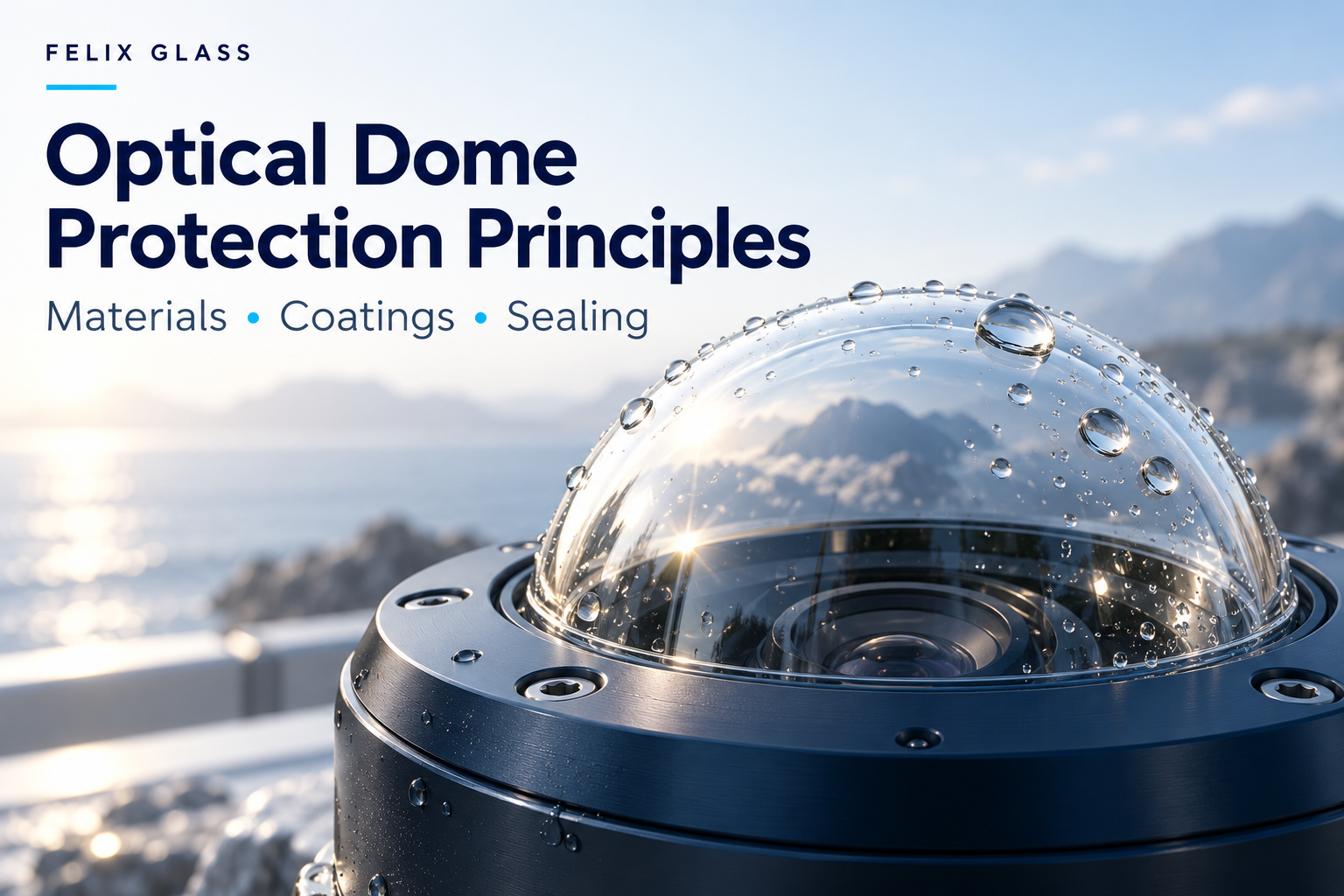
Knowledge Center · LiDAR & Sensing Guide
Optical Dome Protection Principles
How materials, geometry, coatings, seals, and mounting work together to protect optical sensors.
An optical dome separates a sensor from its surroundings while allowing light to pass through a curved surface. Its protective function depends on more than the dome material: the housing interface, coating stack, environmental exposure, and maintenance method all influence performance.
For LiDAR, cameras, and other sensing systems, protection means preserving the optical signal as well as preventing physical damage and ingress. A dome can remain intact yet become unsuitable for sensing because of contamination, distortion, or unwanted reflections.
Explore the Validation Checklist1. Protection Is a Property of the Complete Assembly
A protective dome normally works with a housing, retaining feature, seal, and defined optical alignment. Each part contributes to the barrier between the sensor and the environment.
Physical protection
Resist the specified pressure, impacts, vibration, temperature exposure, and contact loads without unacceptable fracture or deformation.
Optical protection
Maintain usable transmission, beam direction, image quality, and stray-light control throughout the required operating conditions.
Define both sets of acceptance criteria. A leak-free enclosure may still suffer optical failure, while a clean and transparent dome may still have an inadequate seal.
2. Identify the Actual Environmental Threats
| Exposure | Possible failure | Design question |
|---|---|---|
| Rain, spray, or immersion | Ingress, droplet-induced scattering, obscured field of view | What water exposure, pressure, duration, and orientation must the assembly tolerate? |
| Dust, sand, and repeated wiping | Abrasion, coating wear, increased scatter | What particles, contact loads, and cleaning cycles represent service? |
| Impact and vibration | Cracking, edge damage, loosening, alignment shift | What impact energy, contact geometry, vibration profile, and mounting condition apply? |
| Temperature and sunlight | Thermal stress, drift, aging, seal degradation | What operating temperatures, gradients, ramp rates, and UV exposure apply? |
| Salt, oils, and chemicals | Corrosion at interfaces, coating damage, residue, seal swelling | Which substances and concentrations contact the complete assembly? |
| Humidity and condensation | Internal fogging or water films | How will internal moisture and surface temperature be controlled? |
“Outdoor use” is not a complete specification. A sheltered stationary sensor, a road-facing sensor, and an underwater camera require different load cases and test plans.
3. What the Dome Shape Contributes
A spherical shell can provide a broad angular opening while enclosing the sensor. In an ideal concentric dome, a ray through the common center of curvature meets both surfaces normally. Real transmitters and receivers have finite apertures and may be displaced from that center, so optical analysis remains necessary.
Curvature can also support efficient load transfer under distributed pressure. However, a dome is not universally stronger than a flat window: material, radius, wall thickness, edge support, flaws, and the direction of loading all matter.
Evaluate the shell, flange, and mounting transition together. A locally weakened edge or an unfavorable restraint can determine failure even when the main curved surface is sufficiently thick.
For external pressure, assess instability or buckling where relevant, as well as material stress. Do not substitute a flat-window thickness equation for a dome analysis. Manufacturer dome guidance provides useful background on geometry and concentricity, but a specific assembly still needs its own assessment. [1]
4. Select Materials by the Required Failure Resistance
| Material family | Reason to evaluate it | Protection-related limitations to check |
|---|---|---|
| BK7 / H-K9L optical glass | Optical quality and compatibility with many visible and near-infrared designs | Brittle fracture, edge quality, thermal mismatch, and grade-specific properties |
| Fused silica | Low thermal expansion and optical stability | Mounting stress, surface damage, thermal gradients, and actual spectral requirements |
| Sapphire | High surface hardness and abrasion resistance | Crystal orientation, edge flaws, impact loading, optical birefringence, and coating durability |
| Optical-grade polycarbonate | Lightweight construction and impact-tolerant designs | Scratching, creep, molding stress, chemical compatibility, and weathering of the chosen grade |
| Optical-grade PMMA | Lightweight transparent covers with appropriate optical and environmental properties | Impact requirements, chemical sensitivity, surface wear, and temperature limitations |
This table is a screening guide, not a strength ranking. Hardness, impact resistance, and pressure capability are different properties. For every candidate, confirm transmission at the operating wavelength and obtain supplier data for the exact grade.
A hard substrate does not make a softer topcoat scratch-proof. The outermost exposed layer often determines cleaning and abrasion limits.
5. Thickness Must Balance Structure and Optics
Increasing thickness may improve some load-bearing characteristics, but it also changes mass, optical path length, absorption, and the behavior of off-center rays. There is no universal wall thickness suitable for every dome diameter or application.
- Geometry: Define outer and inner radii, minimum wall thickness, dome height, flange dimensions, and edge transitions.
- Loads: Include pressure differential, assembly preload, impact, temperature gradients, and relevant combinations.
- Material data: Use an appropriate basis for the actual material and condition, including brittle-material variability where applicable.
- Optical limits: Check transmitted wavefront or beam deviation and clear aperture under load.
- Verification: Agree on analysis, prototype testing, production inspection, and any proof-test requirement.
For immersion, the approximate hydrostatic pressure increase is Δp = ρgh. Using ρ = 1025 kg/m³ and g = 9.81 m/s², 100 m of seawater adds about 1.01 MPa of external pressure. This is a load estimate only; the actual differential also depends on internal pressure.
A depth-to-pressure calculation does not establish a safe dome thickness or rated operating depth. Those require the geometry, support conditions, material basis, and validation of the complete assembly.
6. Mount the Dome Without Harmful Local Stress
A retaining ring or housing can damage a dome through uneven contact, excessive preload, or an unintended hard point. Differential thermal expansion can change that loading during operation.
Crystran’s pressure-window guidance specifically identifies localized mounting stress and expansion mismatch as concerns. Its flat-window guidance should inform interface design, not be treated as a dome design calculation. [2]
- Use defined support and retention surfaces with controlled geometry and cleanliness.
- Keep burrs, trapped particles, and unintended metal contact away from vulnerable edges.
- Specify assembly preload and sequence; torque alone is an indirect indicator of clamping force.
- Provide a validated way to accommodate thermal expansion differences.
- Keep mounting features outside the required optical aperture and ray paths.
Compliant supports may help manage stress, but they can also permit movement. Verify both mechanical security and optical alignment after assembly and environmental exposure.
7. Seals, Bond Lines, and Ingress Protection
O-rings, gaskets, or adhesive joints must be selected for the fluid, temperature, pressure, geometry, and service life. Groove dimensions, surface finish, seal compression, and tolerance accumulation all influence sealing. Parker’s O-Ring Handbook provides component-level design guidance for these choices. [3]
Do not specify a universal O-ring squeeze or adhesive thickness without evaluating the joint. A bond may also introduce cure shrinkage, thermal stress, optical contamination, and replacement difficulties.
IEC 60529 classifies protection provided by electrical enclosures. A bare optical dome does not independently establish an IP rating for a finished sensor. [4]
Define the required assembled-enclosure test and its conditions. An ingress result is not, by itself, evidence of a structural pressure rating, long-term immersion life, or resistance to every cleaning method.
Pressure-equalizing vents are application-specific. They may help manage enclosure pressure changes, but their suitability for liquids, contamination, and immersion must be confirmed.
8. Give Each Coating a Defined Job
| Treatment | Intended function | What it does not guarantee |
|---|---|---|
| Anti-reflection coating | Reduce reflection over a specified band and angular range | Impact resistance, sealing, or unlimited abrasion life |
| Hardcoat or protective layer | Improve resistance to specified surface wear | Scratch-proof behavior under every abrasive or cleaning process |
| Hydrophobic treatment | Change wetting behavior and support water shedding | A droplet-free surface in all orientations and weather conditions |
| Oleophobic treatment | Reduce wetting or adhesion of selected oily contaminants | Complete protection from fingerprints, chemicals, or residue |
| Anti-fog treatment | Manage condensation behavior by a defined mechanism | Removal of moisture from the enclosure or permanent clarity |
Hydrophobic product families illustrate that water repellency and abrasion durability can involve tradeoffs. Specify retention of performance after the intended exposure and cleaning, not just initial appearance or contact angle. [5]
Test the full coating stack on the actual substrate. A coating suitable for another infrared band is not automatically appropriate for 905, 940, or 1550 nm. Also confirm coating uniformity over curved surfaces and the relevance of any witness samples.
9. Control Rain, Condensation, and Ice at System Level
Water can impair sensing before it enters the enclosure. Droplets and films change the optical interface and can scatter, refract, or obstruct the useful light.
Consider installation orientation, drainage, exposed surface shape, and whether a hood or air-cleaning feature would obstruct the scan. Water shedding should be tested in the intended orientation and airflow.
Internal condensation can occur when a surface falls below the dew point of the enclosed air. Depending on the application, moisture control may involve dry assembly, desiccants, a suitable purge, enclosure design, or controlled heating.
If heaters are used, evaluate thermal gradients, electrical interfaces, energy demand, and sensing-band transmission. A transparent conductive layer or heater pattern can introduce absorption, scatter, or beam artifacts. Validate cold starts and recovery time as well as steady operation.
10. Design for Cleaning and Service
Cleaning is part of the durability requirement. Repeated wiping of a dusty surface can cause damage that does not appear in an initial transmission measurement.
- Inspect the surface and identify contamination before selecting a cleaning method.
- Remove loose particles using an approved noncontact method where appropriate.
- Use only cleaning fluids, materials, and contact pressures qualified for the substrate, coatings, seals, and adhesives.
- Avoid treating a solvent recommended for one glass optic as universally safe for polymers or assembled parts.
- Check for residue and optical degradation after cleaning.
Manufacturer cleaning guidance is a useful starting point, but the finished assembly needs a compatible procedure. [6]
Define permitted cleaning cycles and field replacement criteria. If the dome is replaceable, establish seal replacement, assembly, leak checking, and any recalibration steps needed after service.
11. Verify Optical Performance While Providing Protection
The dome must remain optically acceptable across the full operating field. Measure more than a central transmission value.
- Transmission: Specify the complete wavelength band, local incidence angles, polarization, and clear aperture.
- Beam deviation or imaging: Check scan-dependent steering, wavefront effects, and image performance as applicable.
- Unwanted returns: Assess reflections between the dome, transmitter, receiver, and housing.
- Contamination sensitivity: Evaluate representative droplets, deposits, and cleaning residue.
- Loaded performance: Check whether pressure, mounting stress, or temperature changes the optical behavior.
For a LiDAR beam that passes through the same dome once outbound and once on return, the cover contribution is approximately Tout × Treturn. If each pass transmits 95%, the two-pass contribution is 90.25%, before other system losses. This example is not a detection-range prediction.
12. Build a Validation Plan with Measurable Acceptance Criteria
| Verification | Conditions to define | Results to record |
|---|---|---|
| Baseline inspection | Drawing revision, aperture, test wavelengths, assembly state | Dimensions, surface condition, transmission, and relevant optical errors |
| Ingress and leak testing | Complete housing, medium, pressure or exposure, duration, orientation | Ingress or leakage against the agreed acceptance criteria |
| Pressure testing | Load direction, ramp, hold, cycles, temperature, and approved test procedure | Integrity, deformation, leakage, and optical changes |
| Thermal exposure | Temperature limits, gradients, ramp rates, dwell, and powered state | Cracks, seal condition, alignment, and optical drift |
| Abrasion and cleaning | Contact material, load, contaminants, fluid, and cycle count | Wear, scatter, transmission, and surface-treatment retention |
| Impact and vibration | Representative installed mounting and defined mechanical loads | Damage, retention, leaks, and alignment change |
| Weathering and chemicals | Exposure spectrum or substance, concentration, temperature, and duration | Coating adhesion, haze, discoloration, seal condition, and optical performance |
Distinguish operation during exposure from survival followed by recovery. Passing a post-test measurement does not prove that the sensor remained functional throughout the test.
Set sample quantities, test order, acceptance limits, and any destructive testing before qualification. Freeze the approved configuration and assess subsequent changes to material, coatings, seals, or mounting.
13. What to Include in a Protective Dome RFQ
- Application: LiDAR, camera, or other sensor; air or liquid environment; installation orientation.
- Optical requirements: Wavelengths, field of view, aperture, sensor location, transmission, and beam or image tolerances.
- Drawing: Inner and outer radii, thickness limits, height, flange, datums, edge treatment, and tolerances.
- Material and coatings: Specified grade, permitted alternatives, coated surfaces, and durability requirements.
- Load cases: Internal and external pressures, temperature conditions, impacts, vibration, and expected service cycles.
- Interface: Housing material, support, retaining method, seal or bond design, and assembly restrictions.
- Validation: Agreed test methods, acceptance criteria, reports, and the party responsible for assembly-level qualification.
- Commercial scope: Prototype quantity, production volume, schedule, and whether the request covers the dome alone or an assembly.
A request such as “waterproof sapphire dome for outdoor LiDAR” leaves important details open. A drawing, optical layout, and defined exposure profile provide a stronger basis for a meaningful quotation.
14. Frequently Asked Questions
Does an optical dome make a sensor waterproof?
The dome can form part of a sealed enclosure, but the seals, housing, retention, and assembly process determine the completed barrier. Verify the finished assembly under the required exposure conditions.
Is sapphire always the strongest choice?
No. High hardness supports abrasion resistance, but impact performance and pressure capability depend on geometry, flaws, crystal properties, support, and loading. Compare materials against the actual failure modes.
Can a hydrophobic coating keep a dome completely clear in rain?
No universal guarantee follows from the coating alone. Droplet shedding depends on surface condition, orientation, airflow, contamination, and wear. Test sensor performance in representative rain conditions.
Does increasing wall thickness always improve the design?
No. It changes structural behavior, mass, optical path length, and thermal response. Select thickness through combined mechanical and optical analysis rather than a single rule.
Can an IP rating be used as a deep-water pressure rating?
No. Ingress classification and structural pressure capability are separate requirements. A submerged design needs explicit pressure, duration, cycling, mounting, and validation conditions.
Can the dome carry AR and water-repellent coatings?
Potentially. Confirm compatibility and the transmission and durability of the complete coating stack on the selected material. The combined result must be evaluated across the working angles and wavelengths.
Why can a dome crack during assembly?
Possible causes include uneven seating, particles or burrs, edge damage, excessive preload, or a poorly accommodated thermal mismatch. Inspect the full interface rather than assuming the dome material alone is responsible.
What matters most before volume production?
Qualify representative parts in the intended housing, verify both optical and protective performance, and document the drawing, materials, coatings, seals, assembly method, inspection, and change controls.
15. Discuss Your Custom Protective Dome
Felix Glass supports custom precision optical component projects, including glass and sapphire domes for sensing applications. Share your optical requirements, drawing, environmental conditions, mounting concept, and quantities for a component manufacturability review.
Material, thickness, coatings, tolerances, inspection scope, and delivery conditions should be confirmed for the individual project. Define assembly engineering and qualification responsibilities separately when the supplied scope is the optical component alone.
Dongguan Felix Glass Co., Ltd.
Email: james@felixglass.com