Optical Window & Dome Comparison
- Share
- publisher
- Felix Glass Co., Limited
- Issue Time
- Oct 26,2026
Summary
Compare flat optical window vs concentric spherical dome for LiDAR: FOV, beam performance, pressure, mounting, manufacturing trade‑offs & specification tips.
Knowledge Center · LiDAR & Sensing Guide
Optical Window & Dome Comparison
How to choose between a flat protective window and a curved optical dome for your sensor.
Flat windows and optical domes both separate an optical system from its surroundings. The better choice depends on the ray geometry, available space, environmental loads, and acceptable optical errors—not simply on whether one shape appears stronger or more advanced.
This guide compares their practical tradeoffs for LiDAR, imaging, and industrial sensing, then outlines the information needed to select and specify a custom component.
View the Comparison Table1. Which Geometry Should You Evaluate First?
Start with a flat window when…
The sensor looks through a defined forward aperture, a planar seal fits the housing, and optical performance remains acceptable across the required field.
Evaluate a dome when…
A broad angular field or moving optical head benefits from a curved cover, and the sensor can be positioned appropriately relative to the dome geometry.
A wide field does not automatically require a dome, and a pressure requirement does not automatically rule out a flat window. Use these starting points to build a shortlist, then compare optical models and mounted-component performance.
2. What Is Being Compared?
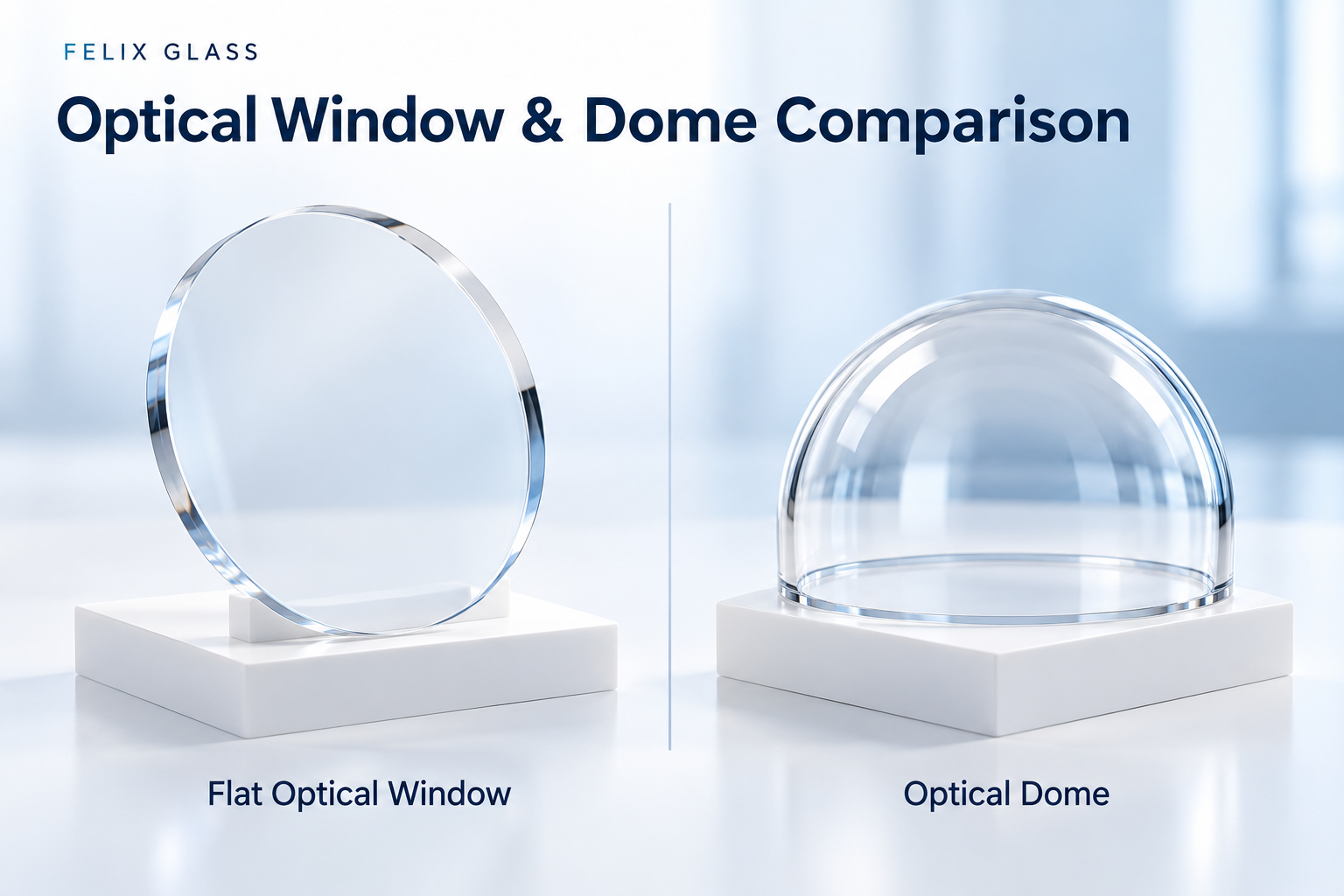
A flat optical window has two nominally planar transmitting surfaces. They are often parallel, although a specified wedge may be introduced to redirect reflections or manage interference.
An optical dome is a curved protective shell. This article primarily considers a spherical dome with concentric inner and outer surfaces. Cylindrical covers, freeform covers, and intentionally nonconcentric domes require their own optical analysis.
A dome is also a type of optical window in the broader sense. Here, “window” means the flat geometry so the comparison remains clear. Surface quality, material homogeneity, and mounting stress matter for both. [1]
3. Flat Window vs. Optical Dome: Comparison Table
| Selection factor | Flat optical window | Concentric spherical dome |
|---|---|---|
| Field of view | Often convenient for a forward-looking aperture; large fields can require a larger opening and high-angle coating performance. | Can provide broad angular access around a suitably positioned sensor; rims and mounts still limit usable coverage. |
| Ray direction | An ideal parallel plate in the same surrounding medium preserves the emerging ray direction, with lateral displacement at oblique incidence. | Rays through the common center meet both surfaces normally; other rays can be refracted. |
| Optical errors | Focus shift and aberrations can arise in converging or diverging beams. | Errors depend on radii, concentricity, pupil position, finite aperture, and surrounding media. |
| AR coating | Planar coating and inspection are often straightforward, but performance must cover the actual angles. | Both local incidence angles and coating uniformity across the curved surface require attention. |
| Pressure | Plate bending, stress, and support conditions are important. | Shell behavior, edge restraints, imperfections, and possible external-pressure instability are important. |
| Mounting | Often fits a relatively simple planar retaining and sealing interface. | Typically needs a defined rim or flange interface and alignment to the optical center. |
| Inspection | Flatness, wedge, thickness, and transmitted wavefront are common checks. | Radii, surface form, thickness variation, concentricity, and angular optical performance are common checks. |
| Cost | Often the simpler starting point for comparable polished-glass requirements. | Curved processing, tooling, coating, and metrology may add cost; volume and production route can change the comparison. |
This is a qualitative engineering comparison, not a guaranteed performance or cost ranking.
4. Field of View and Aperture Size
For a flat cover, rays at the edge of a wide field generally encounter a larger incidence angle than central rays. The required aperture also grows with distance between the optical pupil and the cover.
As a simple geometric estimate in air, before accounting for window refraction, a centered pupil with radius r located a distance d behind a plane needs an aperture radius of at least r + d tan θ for a symmetric half-field angle θ. This is only a preliminary envelope: add the actual beam geometry, tolerances, and mounting clearance in the optical model.
A concentric dome can keep selected rays closer to normal incidence if their effective origin lies near its center. That benefit depends on actual placement. Separate transmitter and receiver pupils, scanning mirrors, and finite beam footprints may not share a common center.
Check the entire transmitted and received ray bundles. A cover that clears the laser beam may still vignette the receiver or an adjacent camera.
5. How a Flat Window Changes the Optical Path
For an ideal plane-parallel plate in the same medium on both sides, refraction at the second surface restores the ray’s original direction. At oblique incidence, however, the emergent ray is displaced sideways. Edmund Optics provides a calculator for this effect. [2]
t is plate thickness, i is the incidence angle, and r is the refracted angle inside the plate. For a plate in air, approximately sin r = sin i / n.
For illustration, a 3 mm plate with refractive index n = 1.5 at 45° incidence produces about 0.99 mm of lateral displacement. This is a calculated geometric example, not a component specification.
A parallel plate also changes optical path length. In a converging beam, it can shift focus and introduce aberrations. Therefore, “no net angular deviation” does not mean “no effect on imaging.” A wedged window intentionally changes the direction behavior and must be modeled separately.
6. How a Dome Changes the Optical Path
A radial ray through the common center of a concentric spherical shell meets both surfaces normally. This explains why placing a suitable optical pupil near the center can help a wide-field design.
It does not make the dome optically invisible. Finite ray bundles include nonradial rays, and real systems have alignment offsets, surface errors, and thickness variation. Manufacturer guidance highlights both concentricity and pupil position as design concerns. [3]
- Center mismatch: Displacement of the sensor or pupil changes how rays meet the surfaces.
- Surface mismatch: Nonconcentric inner and outer surfaces can produce unwanted optical effects.
- Finite aperture: Chief-ray behavior alone does not establish image quality or received signal quality.
- Mechanical errors: Flange runout and mounting tilt can affect the assembled optical relationship.
Evaluate the full ray bundle and the tolerances of the mounted dome. Do not specify “zero distortion” without defining how it is measured and the allowable error.
7. Air and Underwater Use Require Different Analysis
When water is outside and air is inside, the surrounding refractive indices differ. The simple same-medium result for a flat parallel plate no longer applies: a flat port can change angular mapping and the camera’s effective field of view.
A suitably positioned dome can help preserve angular coverage, but finite-aperture imaging still needs attention. Refraction can create a virtual object that changes the lens focusing requirement, and image quality can vary across the field.
Include the external medium, dome radii, material index, pupil location, and lens focusing capability in the model. An assembly qualified optically in air should not be assumed to perform identically underwater.
For underwater sensing, also evaluate propagation loss at the chosen wavelength. A mechanically sound port cannot compensate for an unsuitable sensing wavelength or an inadequate underwater signal budget.
8. Materials and Coatings Are Separate Design Decisions
Both geometries can use materials such as optical glass, fused silica, sapphire, or qualified optical polymers. Select the exact grade from wavelength, environment, manufacturing route, and cost requirements.
Do not compare a coated sapphire dome with an uncoated polymer window and attribute the entire difference to shape. To isolate the geometry tradeoff, first compare equivalent material and performance assumptions.
For AR coatings, specify wavelength band, polarization, coated faces, and local incidence-angle range. A flat window’s mechanical angle and a dome’s scan angle are not interchangeable coating specifications.
On a dome, validate coating performance over the useful curved area. On either shape, qualify added hardcoats, hydrophobic treatments, heaters, or printed masks as part of the complete optical stack.
9. Pressure, Impact, and Structural Protection
A flat window and a dome carry loads differently. Neither has an operating-depth or pressure rating based on shape alone.
For a flat window, bending and support conditions can dominate the design. For a dome, shell stress, rim loading, geometric imperfections, and external-pressure stability may be important. Internal pressure and external pressure are different load cases.
Compare the same clear aperture, pressure differential, load duration, cycling requirement, temperature, and material basis. Include assembly preload and possible local stress concentrations.
Crystran’s pressure-window guidance warns that localized mounting stress can cause failure and that material variability affects design decisions. Its flat-window formulas should not be transferred directly to a dome. [4]
Also separate hardness from impact resistance. A scratch-resistant material can still fracture under a particular impact. Confirm the intended assembly through an appropriate analysis and test plan.
10. Mounting, Sealing, and Maintenance
| Assembly question | Flat window considerations | Dome considerations |
|---|---|---|
| Sealing interface | Planar edges or faces can suit simple gasket or O-ring arrangements. | Rim or flange geometry must define sealing, support, and retention. |
| Alignment | Control tilt, wedge orientation, aperture position, and mounting distortion. | Control the relationship between surface centers, flange datums, and sensor position. |
| Cleaning | Access can be straightforward, depending on the enclosure. | Curvature and rims can change wiping access and water drainage. |
| Replacement | Check seal seating and any optical or angular calibration. | Re-establish optical-center positioning as well as seal integrity. |
Both require compatible seal materials and allowance for thermal expansion differences. Keep particles, burrs, and unintended hard contacts out of the load-bearing interface.
An IP classification applies to the relevant assembled enclosure, not to a bare optic’s geometry. Define ingress and pressure requirements separately. [5]
11. Manufacturing Cost and Inspection
For comparable custom polished-glass specifications, a flat window often offers simpler processing and metrology. A dome may need specialized tooling, curved-surface polishing, coating fixtures, and alignment-sensitive inspection.
This tendency is not a fixed price rule. A demanding flat window can cost more than a high-volume molded dome, and a large aperture or tight transmitted-wavefront requirement can change either quotation substantially.
- Flat window drawing: Specify dimensions, thickness, clear aperture, flatness or transmitted wavefront, wedge or parallelism, and edge treatment.
- Dome drawing: Specify radii, height, wall-thickness limits, concentricity, surface form, flange datums, and angular clear aperture.
- Both: Define surface quality, spectral performance, test conditions, reports, and acceptance criteria.
Compare total project cost, including assembly, qualification, yield, maintenance, and calibration. Avoid tightening every tolerance equally; connect each limit to a functional requirement.
12. Application-Based Selection Examples
| Application scenario | Starting candidate | Decision-making check |
|---|---|---|
| Forward-looking industrial distance sensor | Flat window | Transmission and unwanted reflections across the actual beam and receiver fields |
| Wide-angle scanning LiDAR | Dome or another curved cover | Scan origin and receiver pupil position relative to the cover geometry |
| Fixed narrow-field underwater camera | Flat port as one candidate | Acceptable field change, focus, image quality, and pressure performance |
| Wide-angle underwater imaging | Dome port as one candidate | Pupil alignment, virtual-image focusing, edge image quality, and pressure qualification |
| Multisensor enclosure with separated apertures | Separate flat windows or a shared curved cover | Whether all optical channels can meet their requirements through the proposed geometry |
| Sensor with frequent field cover replacement | Compare both as serviceable assemblies | Replacement cost, seal reliability, alignment repeatability, and recalibration |
These are screening examples rather than final recommendations. Packaging constraints or an existing optical prescription can change the preferred solution.
13. A Practical Selection and RFQ Checklist
- Define the optics: Wavelengths, field of view, pupil locations, beam footprints, and operating media.
- Set acceptance limits: Transmission, beam deviation, image quality, crosstalk, and calibration stability.
- Model both candidates: Include the real material, surfaces, coatings, and tolerances.
- Define the environment: Pressure, temperature, impact, vibration, contamination, and cleaning.
- Design the interface: Housing, support, seal, retention, and maintenance access.
- Prototype and compare: Test optical performance and protection in the intended assembly.
- Freeze the production definition: Agree on drawings, inspection, validation, and change control.
For quotation, provide drawings or an initial envelope, material preferences, operating conditions, prototype quantity, annual demand, and required documentation. State whether you want a component only or an assembly-level proposal.
14. Frequently Asked Questions
Is a dome always better for wide-angle LiDAR?
No. A dome can help when its geometry and the sensor layout are coordinated. Separate pupils, packaging constraints, coating requirements, and alignment tolerances can favor a different cover.
Does a flat window change the direction of a laser beam?
An ideal parallel plate in the same medium on both sides preserves the emergent ray direction but causes lateral displacement at oblique incidence. Wedge, surface errors, or different surrounding media change this result.
Does a concentric dome have zero optical effect?
No. Rays through its common center meet the surfaces normally, but a real finite beam contains other rays. Optical path, imaging, alignment, and surrounding media must still be considered.
Which geometry has higher transmission?
There is no shape-only answer. Transmission depends on material absorption, path length, coating, local angles, polarization, and contamination. Compare finished components under the same relevant conditions.
Which geometry withstands more pressure?
The answer depends on dimensions, material, support, imperfections, loading direction, and acceptance criteria. Dome shell behavior can be advantageous, but it does not establish a pressure rating without analysis and validation.
Is a dome always more expensive?
No. Custom precision dome processing can add cost, but production volume, material, molding or polishing route, size, and inspection requirements determine the actual comparison.
Can I replace a flat window with a dome without changing the sensor?
Not automatically. Reassess ray paths, optical alignment, focus or calibration, coatings, housing, seals, and environmental performance.
What is the best way to make the final decision?
Compare optical models using the actual sensor geometry, evaluate the mounted mechanical design, and test representative prototypes against the same functional requirements.
15. Discuss Your Optical Window or Dome Project
Felix Glass supports custom precision optical windows and domes. Share your drawing, wavelength, field of view, mounting concept, environmental loads, and quantities for a component manufacturability and specification review.
If the geometry is still open, provide the transmitter and receiver layout and the available housing space. Confirm the proposed material, tolerances, coating performance, inspection scope, and project responsibilities before manufacture.
Dongguan Felix Glass Co., Ltd.
Email: james@felixglass.com