ZnS Infrared Window Explained
- Share
- publisher
- Felix Glass Co., Limited
- Issue Time
- Oct 24,2026
Summary
This guide explains ZnS infrared protective windows, comparing standard and multispectral grades, transmission‑thickness relationship, AR and DLC coating requirements, optical‑mechanical tolerances, thermal camera integration and specification checklist for infrared system design.
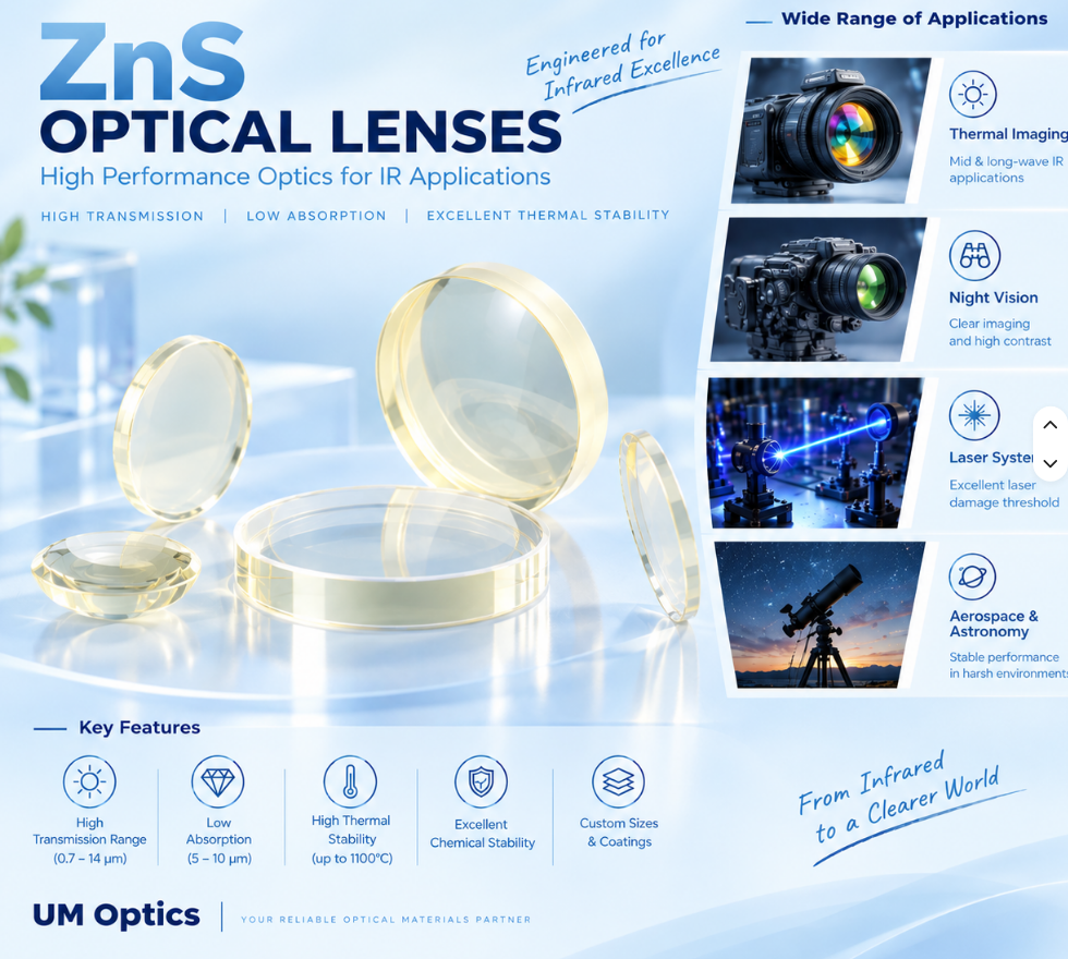
A zinc sulfide (ZnS) infrared window protects an optical system while transmitting the wavelengths needed for imaging or sensing. Its performance depends on the material grade, thickness, surface quality, coating and mounting conditions—not simply the name “ZnS.” This guide explains the difference between standard and multispectral zinc sulfide, how to interpret transmission data, and what to specify when developing a protective window for an infrared camera or multispectral instrument. A ZnS window is an optical component made from zinc sulfide, usually with two nominally flat surfaces. It separates an instrument from its surroundings while allowing selected infrared radiation to pass through. Unlike a lens, a plane-parallel window has no intended focusing power. Nevertheless, its thickness, tilt, surface errors and position can alter an imaging system. A flat plate in a converging beam can shift focus and introduce aberrations; a wedged plate can change beam direction. Typical design roles include a front cover for a thermal camera, an environmental barrier for an industrial sensor, or a shared aperture for instruments operating in multiple spectral bands. Each role requires its own optical and mechanical specification. Optical zinc sulfide is commonly produced by chemical vapor deposition (CVD). The resulting material is polycrystalline rather than ordinary glass. Multispectral material receives additional processing, typically hot isostatic pressing (HIP), to improve optical clarity and reduce scattering [1]. Processing history matters because nominally identical chemical composition does not guarantee identical optical behavior. Specify the optical grade and relevant acceptance criteria rather than relying on “ZnS material” alone. A material certificate should identify the supplied grade and traceability information. When a drawing requires an exact proprietary material, confirm that the actual material meets that requirement before substituting a generic grade. Supplier data show that optical and mechanical properties can change with conversion processing [2]. Multispectral ZnS is therefore not automatically the better choice for every window. Compare the properties relevant to the application rather than treating the grade name as a quality ranking. CLEARTRAN® is a trade name associated with a particular multispectral form of zinc sulfide [2]. It should not be used as a blanket certification that every generic multispectral ZnS product is identical. If an approved drawing calls for CLEARTRAN, the procurement specification should state whether equivalents are allowed. An equivalent-material proposal should compare the required spectral transmission, scattering, homogeneity, mechanical behavior and traceability. For a new design without a mandated brand, define measurable requirements first. This allows material options to be evaluated against the actual system needs. Published multispectral ZnS ranges differ between suppliers and reporting conventions. Coherent describes operation from 0.4 to 12 µm [1], while Crystran lists a nominal range of 0.37 to 13.5 µm [3]. These statements are not interchangeable guarantees for a finished window. A quoted endpoint may reflect a low transmission threshold rather than high usable throughput. For example, Hellma specifies one range using a 10% transmission limit at 6 mm thickness [2]. Always check what a wavelength range actually means. For an ideal lossless air-to-material interface at normal incidence, reflectance is R = ((n − 1)/(n + 1))². Using a representative ZnS index near 2.20 at 10 µm [3], this gives approximately 14.1% reflection at a single uncoated interface. The directly transmitted first pass through two ideal interfaces is about 73.9%, before bulk absorption. If all incoherent internal-reflection contributions are collected for a parallel plate, the ideal total is about 75.3%. These calculations illustrate interface losses; they are not finished-window specifications. Bulk transmission follows the simplified Beer–Lambert relation: Tinternal(λ) = exp[−α(λ)t] Here α is absorption coefficient and t is optical path length in matching units. For a hypothetical α of 0.20 cm−1 and t of 0.50 cm, internal transmission is approximately 90.5%. This example excludes coating losses, reflection and scatter, and applies only where the assumed absorption coefficient is valid. A thicker window can therefore improve mechanical stiffness while reducing throughput. Evaluate both effects at the proposed thickness rather than scaling a thin-sample transmission curve by assumption. An anti-reflection coating reduces reflection within a specified band and angular range. The coating should be designed for the substrate and for the actual ray angles at the window. Separate three commonly confused quantities: A requirement such as “average transmission ≥95%” must state whether it applies to the complete window, the spectral interval, angle of incidence and averaging method. A low-reflection coating cannot eliminate absorption inside the substrate. For a multi-band window, specify each band separately. A coating optimized for LWIR may not preserve visible imaging quality, even when the uncoated substrate is visibly clear. An exposed surface may need a protective hard-carbon or DLC coating, while the internal surface uses a broadband AR coating. Treat this as a complete coating-system design, not an automatic recipe for every ZnS window. Confirm compatibility with the actual ZnS grade, coating stress, adhesion, optical loss and environmental exposure. Depending on its design, a protective stack may also control reflection; the label “DLC” alone does not specify that performance. A useful drawing identifies: If a customer specifies a coating standard, include the applicable revision, relevant tests and pass/fail criteria. Do not claim conformity from a coating name alone. A witness coupon can support process verification, but geometry-dependent performance may require testing the finished component. Thickness cannot be chosen from outer diameter alone. Mechanical loading depends on unsupported aperture, support geometry, pressure difference, preload, edge condition, temperature gradients and material variability. Distinguish three dimensions: the overall outside diameter, the optical clear aperture and the unsupported mechanical span. They may be different, and each affects a different part of the design. Specify operating loads and environmental conditions before selecting a thickness. Review the mount and seal as an assembly, including differential thermal expansion and allowable window deflection. A window that remains intact can still deform enough to affect image quality. For pressure-bearing applications, use an appropriate mechanical analysis and qualification test. A generic material-strength value or a previously used thickness is not a pressure rating for a new assembly. A scratch/dig value does not establish flatness or image resolution. Similarly, two individually flat surfaces do not automatically guarantee a specified transmitted wavefront if wedge, thickness variation, inhomogeneity or mounting stress are present. When a drawing states “λ/4 at 632.8 nm,” clarify whether it refers to surface form or measured wavefront and whether the condition applies before or after coating. Avoid converting between these definitions without the test geometry. Test a protective window as part of the optical train. It can change focus, vignetting, ghost reflections and the available signal. Include the most oblique field rays when checking clear aperture and coating response. For radiometric cameras, window transmission and window temperature can affect measured temperatures. The camera may need compensation or recalibration with the final window installed. FLIR identifies intervening optics and environmental parameters as relevant to radiometric setup [4]. High image contrast does not prove accurate temperature measurement. Verify imaging performance and radiometric accuracy separately against the application requirements. Practical validation should include the intended working distances, field positions, temperatures and illumination conditions. Contamination, condensation and water films should be considered when they are realistic operating conditions. Material substitution should follow the required wavelengths and environment. A mechanically robust material is not useful if it blocks the detector's operating band. Even for a nominally flat window, changing material changes optical path length, interface reflection, coating requirements and thermal behavior. Review the assembly rather than replacing only a material name on the drawing. Illustrative drawing entry: “Multispectral ZnS window; Ø75 mm × 5 mm; clear aperture Ø67.5 mm minimum; S1 external protective coating; S2 internal BBAR; complete-part transmission over 8–12 µm to an agreed specification.” This example still requires tolerances, optical-quality limits, coating qualification and an achievable transmission target before release. Use “≥90% of diameter” if that is the intent. An aperture of 90% of diameter represents only 81% of the full circular area; diameter and area percentages are not interchangeable. No. It is particularly useful when visible clarity and low scatter across multiple bands matter. Mechanical properties, coating needs and the actual infrared band may support a different selection. No. CLEARTRAN is a trade name. Confirm whether the drawing requires that exact material or permits an approved equivalent. Suitable multispectral grades can support both. The finished window must also have coatings and optical quality compatible with each channel. No. Verify actual thickness, material grade and coating, particularly near the long-wavelength edge. A nominal range does not define a minimum transmission value. That requires a case-specific assessment. Define the band, averaging method, thickness and complete coating stack. Do not promise a finished-window value from a coating reflectance specification alone. Additional thickness generally increases stiffness, but also changes absorption, mass and optical path. The appropriate thickness balances mechanical and optical requirements. It can. The window modifies the signal and may contribute thermal emission. Validate the final installation and apply the camera manufacturer's supported compensation or calibration method. Use the approved procedure for the actual coating and assembly. Handle by the edges with clean gloves, remove loose particles before contact cleaning, and avoid unapproved solvents or abrasive wiping. For a custom infrared window project, share the operating wavelengths, drawing, material grade, coating requirements and environmental conditions. These details allow the proposed optical and mechanical specifications to be reviewed together. Felix Glass focuses on custom precision optical components. Feasibility, finished-part performance, inspection scope and delivery should be confirmed against the final drawing and agreed acceptance criteria. Send your PDF drawing and STEP file, if available, together with prototype and production quantities. Identify any requirements that are mandatory and any that are open to engineering recommendations. Discuss Your ZnS Window Project Email: james@felixglass.com Other topics in this series: Infrared Imaging Principles; Germanium (Ge) Lens Guide; IR Transmission Range Guide (8–15 µm); Infrared Optical Material Comparison. Reference material values and explanatory calculations are not finished-component guarantees. Use agreed specifications and measured data for design acceptance.ZnS Infrared Window Explained
1. What Is a ZnS Infrared Window?
2. How Optical ZnS Is Produced
3. Standard ZnS vs Multispectral ZnS
Selection factor Standard / FLIR-grade ZnS Multispectral ZnS Optical appearance Typically less visibly clear; appearance varies with processing and thickness Typically water-clear before coatings Primary selection reason Infrared transmission with suitable mechanical properties Reduced scatter and transmission across multiple bands Visible imaging or alignment Do not assume adequate visible image quality Often selected when a useful visible channel is required Mechanical properties May offer higher hardness and flexural strength than the converted grade Optical improvement does not imply greater strength Qualification Verify the intended IR band and actual grade Verify every required band, including scatter-sensitive channels 4. What Does CLEARTRAN Mean?
5. Understanding the ZnS Transmission Range
6. Reflection, Absorption and Thickness
7. AR Coatings and Complete-Window Transmission
8. DLC on the Outside and AR on the Inside
9. Selecting Window Thickness and Mounting Geometry
10. Optical Quality: Flatness, Wavefront and Wedge
Specification What it describes What to clarify Surface quality Scratches and digs under a defined inspection method Inspection standard and usable aperture Surface flatness Departure of a surface from the specified plane Test wavelength, PV/RMS convention and aperture Transmitted wavefront error Optical-path distortion through the component Test wavelength, mounting and removed terms Wedge / parallelism Relative angle between the faces Angular units, tolerance and orientation Scatter / haze Redistribution of light away from the desired path Wavelength and measurement geometry 11. Integrating a ZnS Window into a Thermal Camera
12. ZnS Compared with Other Window Materials
Material Main review question Required verification ZnS Standard or multispectral grade? Band transmission, scatter, strength and coating compatibility ZnSe Does its optical and mechanical performance suit the exposure? Thickness-specific throughput and durability Germanium Does the thermal behavior fit the system? Operating-temperature transmission and visible-channel limitations Sapphire Is the required band within its useful transmission range? Do not treat it as an ordinary 8–14 µm substitute Silicon Is the grade suitable for the precise IR band? Measured spectral performance; no assumed full-band LWIR equivalence 13. ZnS Window Specification Checklist
14. Frequently Asked Questions
Is multispectral ZnS always better than standard ZnS?
Is every multispectral ZnS window CLEARTRAN?
Can ZnS transmit visible light and thermal infrared?
Does ZnS guarantee high transmission across 8–14 µm?
Can a DLC-coated ZnS window achieve 95% transmission?
Does adding thickness always improve the window?
Will adding a ZnS cover affect thermal camera calibration?
How should a coated ZnS window be cleaned?
15. Discuss Your ZnS Window Requirements with Felix Glass
Request a ZnS Window Engineering Review
Dongguan Felix Glass Co., Ltd.Continue Reading
Technical References