Electrical and Optical Trade-Off
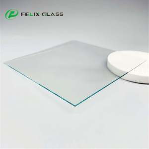
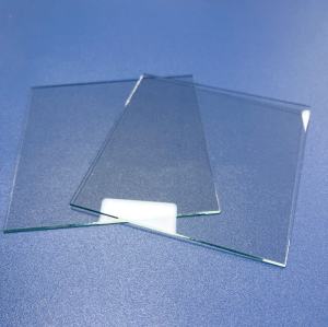
A lower sheet-resistance target may affect optical transmission, color and coating design. One isolated number cannot define the product.

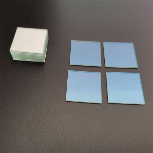
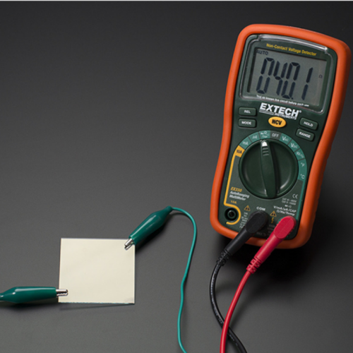
ITO Glass for Medical Equipment & Laboratory Systems
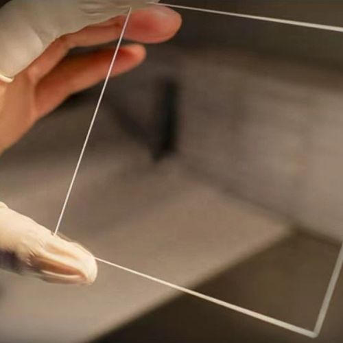
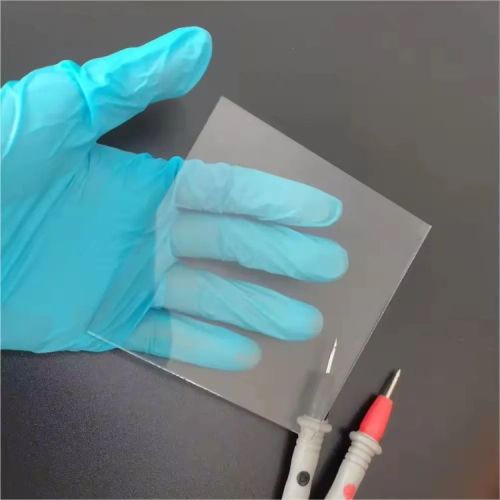
Custom transparent conductive glass for medical displays, touch interfaces, sensors and diagnostic instruments.
Dongguan Felix Glass Co., Ltd. supplies drawing-based ITO conductive glass with project-specific substrate, sheet-resistance target, optical requirements, electrode pattern, busbar, edge finishing and inspection criteria.

Buyer & Engineering Risks
The conductive coating is only one part of the design. Electrical uniformity, optics, pattern geometry and assembly compatibility must be defined together.
A lower sheet-resistance target may affect optical transmission, color and coating design. One isolated number cannot define the product.
Unclear electrode geometry, busbar, contact area or keep-out zones can cause assembly and functional failures.
Uncontrolled substrate, inspection methods or revision changes can delay validation and repeat production.
Requirement-to-Part Translation
Each solution links the design risk to a measurable drawing or inspection requirement.
Capability: sheet-resistance and optical requirement review. Solution: define Ω/sq target together with wavelength, transmission method and permitted visual appearance. Buyer benefit: fewer conflicting specifications.
Capability: drawing-based pattern and busbar review. Solution: confirm active area, isolation gap, edge exclusion, contact pads and orientation. Buyer benefit: improved assembly readiness.
Capability: revision control and agreed inspection plan. Solution: establish the approved sample, reporting scope and packaging requirement before production. Buyer benefit: clearer acceptance and change control.
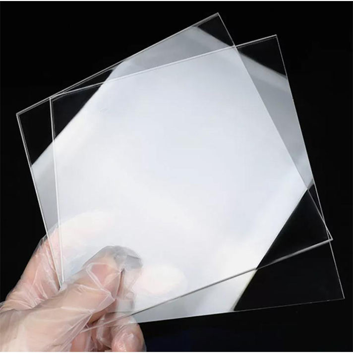
Five-Part ITO Architecture
These five dimensions form the quotation and validation baseline.
Glass type, thickness, size, flatness, edge finish and thermal or chemical requirements.
ITO side, sheet-resistance target, uniformity requirement and measurement method.
Transmission wavelength, haze, color, reflectance and cosmetic acceptance criteria.
Active area, etched isolation, line/space feasibility, contact pads, busbar and orientation.
Bonding zones, cleaning, packaging, traceability and mutually agreed test records.
Typical Product Configurations
Configurations are starting points only. Final construction is defined by the customer drawing and system requirements.

Transparent conductive glass for display, control and sensing interfaces.
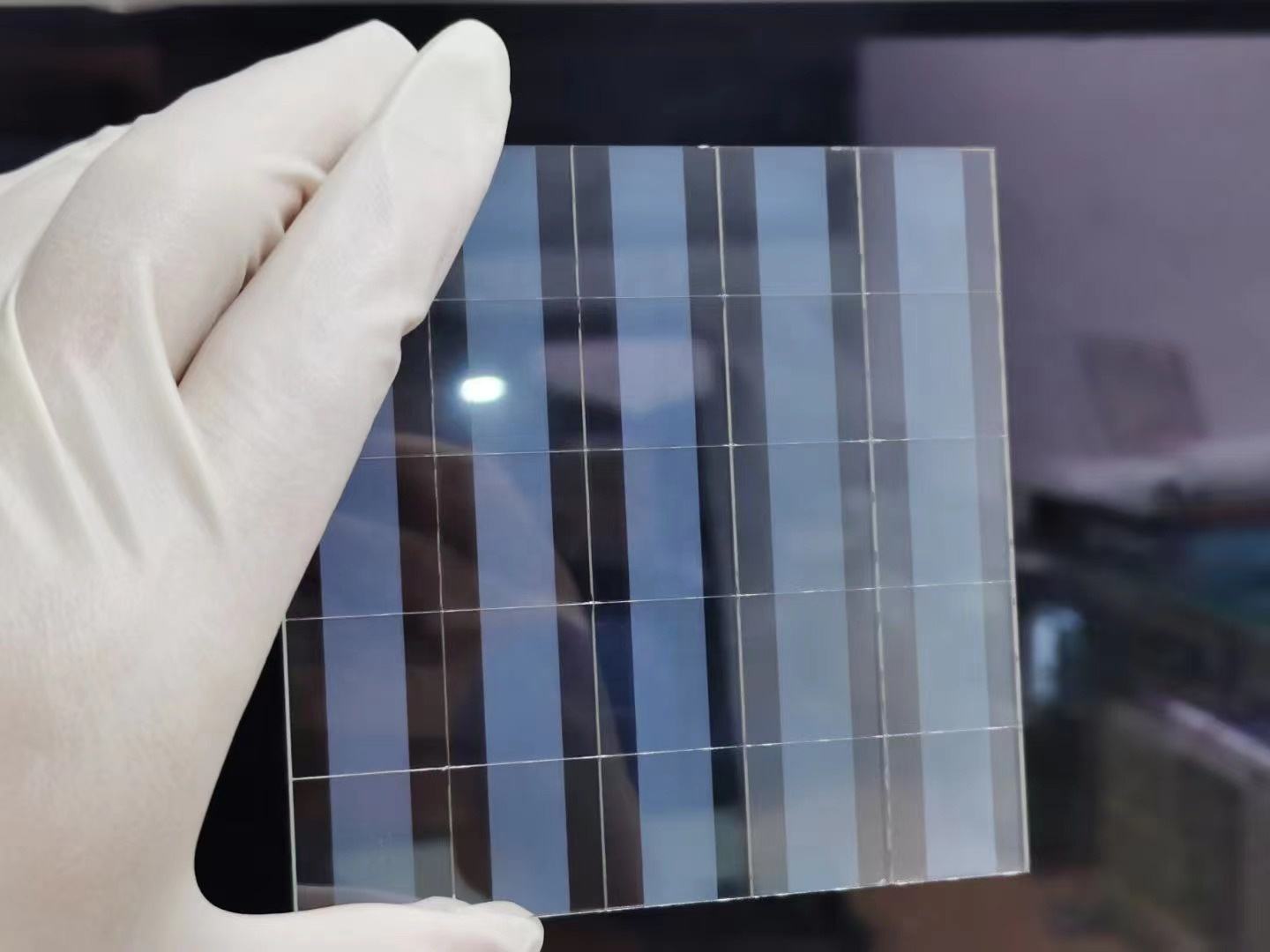
Drawing-defined conductive areas and isolation geometry for custom circuits.
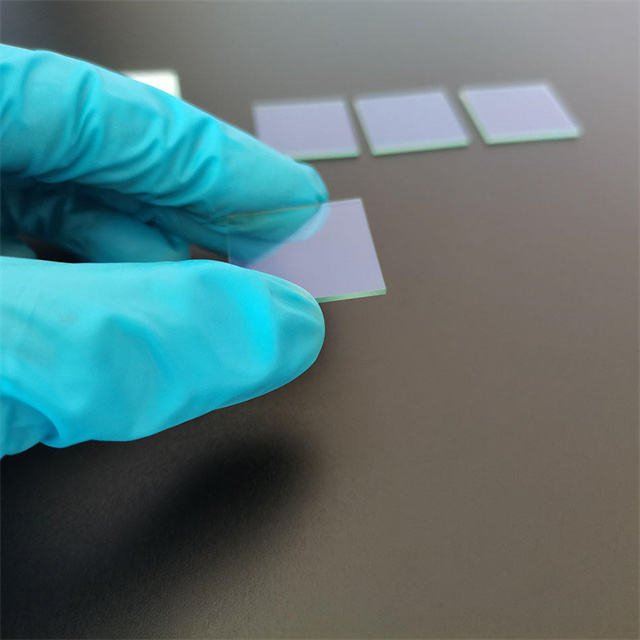
Conductive optical substrates for analytical, sensing and research assemblies.
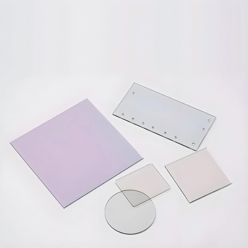
Conductive glass combined with drawing-defined mask, legend or border printing.
Specification Checklist
No universal resistance, transmission, tolerance or MOQ is claimed. Provide the functional target and measurement method.
| Specification | Information to Provide | Quotation / QC Relevance |
|---|---|---|
| Application | Medical display, diagnostic instrument, laboratory sensor, touch interface or other equipment | Defines functional and documentation priorities |
| Substrate | Glass type, thickness, overall size, shape and any approved equivalent | Controls optics, processing, availability and cost |
| Sheet Resistance | Target in Ω/sq, permitted range, test points and measurement method | Defines the conductive-layer acceptance criterion |
| Optical Requirements | Wavelength, transmission/haze/color target and test method | Prevents ambiguous optical claims |
| ITO Pattern | Active area, isolation lines, line/space, edge exclusion, pads and orientation | Determines patterning feasibility |
| Busbar / Printing | Material, geometry, resistance target, color, adhesion and curing limitations | Supports electrical connection and visual integration |
| Mechanical Processing | Size tolerances, holes, slots, chamfers, corners, edge finish and datum scheme | Defines fit and handling safety |
| Surface & Cleanliness | Cosmetic criteria, handling, particle/contamination limits and protective film | Establishes inspection and packing controls |
| Documentation | Drawing revision, material declaration, inspection report and change-notice expectations | Supports customer design-control requirements |
| Procurement | Prototype quantity, production forecast, destination and target schedule | Supports MOQ, lead-time and packaging evaluation |
“Medical grade” on this page describes the intended equipment market and controlled customization. It does not, by itself, claim ISO 13485 certification, biocompatibility, sterility, implant suitability or regulatory approval.
Industry → Equipment → Interface → ITO Glass
The ITO glass is supplied as an engineered component for integration by the equipment manufacturer.
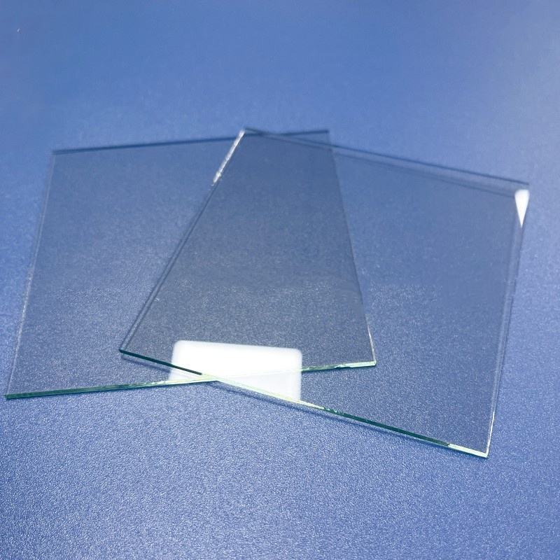
Manufacturing & Verification
The actual process route is confirmed from the substrate, conductive-layer requirement, pattern, printing, dimensions and inspection plan. We do not claim that every operation is performed in-house.
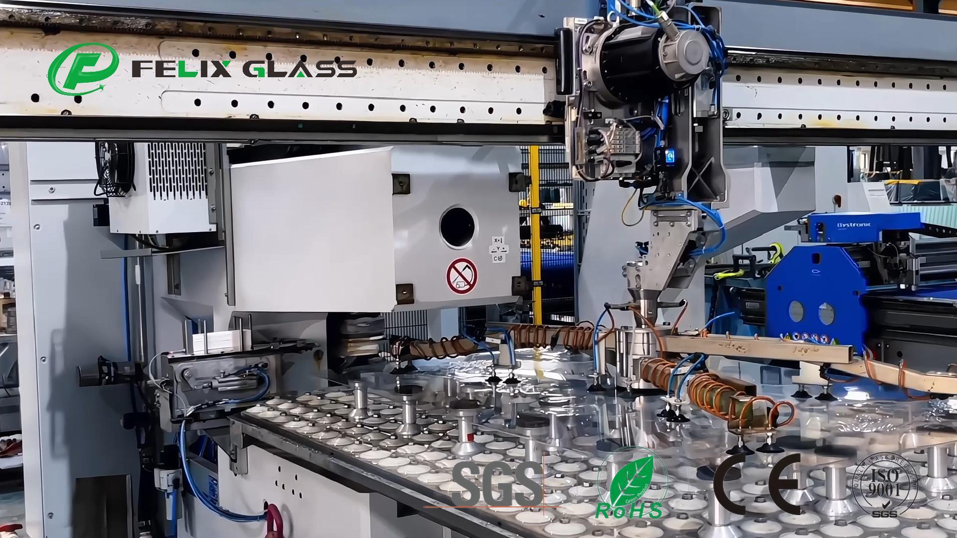
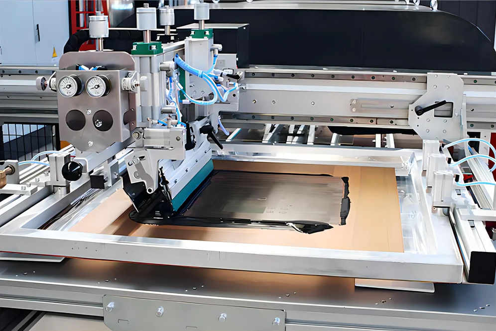
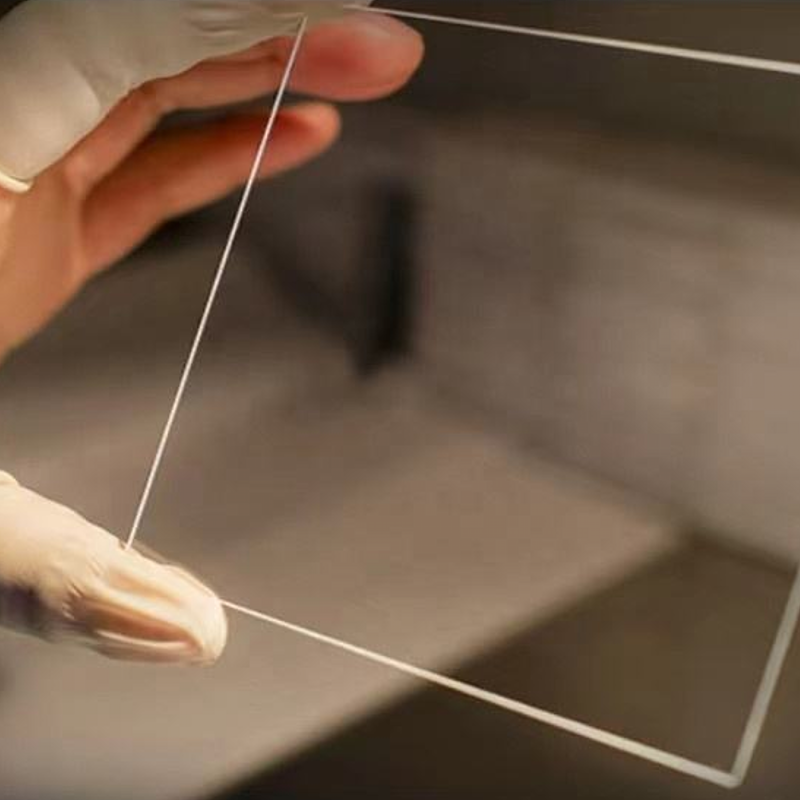

Dongguan Felix Glass Co., Ltd. provides drawing review, glass processing and coordinated project delivery.
Custom sizing, profile, holes, slots and edge treatments are evaluated against the substrate and ITO layer.
ITO patterning, isolation, busbar and decorative printing options are reviewed for project feasibility.
Sheet resistance, dimensions, appearance and optical checks are defined by mutually agreed criteria.
Validation-Gated Delivery
The customer retains responsibility for finished-device validation and regulatory compliance.
Application, drawing, electrical, optical and documentation needs are checked.
Substrate, pattern, tolerances, exceptions and inspection methods are clarified.
Prototype parts are prepared against the agreed revision.
The customer evaluates electrical, optical, assembly and device-level performance.
Repeatability, reporting, packing and handling are confirmed.
Repeat orders follow the controlled drawing and approved requirements.
Agreed electrical, optical, dimensional and cosmetic checks are completed.
Conductive surfaces and contact areas are protected for transport and handling.
Product-Specific Process
Only the operations required by the approved construction are included.
Confirm glass, thickness, conductive side, sheet-resistance and optical targets.
Prepare the drawing-defined outline, holes, slots, corners and edges.
Create or source the approved active areas, isolation and contact geometry.
Apply the agreed electrical or visual printing where required and feasible.
Verify agreed criteria and protect the conductive surface for shipment.
Related Functional Glass
Use a dedicated product path when the requirement is driven by another surface function.
Engineering & Procurement FAQ
Project-specific answers avoid misleading universal performance claims.
It means custom ITO glass intended for integration into medical or laboratory equipment with controlled drawing, inspection and documentation requirements. It does not automatically mean the glass is sterile, biocompatible, implantable, ISO 13485 certified or approved as a finished medical device.
Provide the target and permitted range in Ω/sq, measurement method, test locations, substrate and optical requirements. Feasibility is confirmed after the complete specification is reviewed.
Patterned areas, isolation gaps, contact pads and keep-out zones can be reviewed from DXF, Gerber or dimensioned drawings. Minimum feature feasibility depends on the construction and process route.
Busbar and functional or decorative printing options can be evaluated. Provide artwork, dimensions, resistance or adhesion requirements, color target and curing restrictions.
Availability depends on thickness, size, optical requirement, ITO construction and supply route. State the preferred substrate and whether an equivalent may be proposed.
MOQ depends on substrate, ITO coating, patterning, tooling, printing and inspection scope. Include both prototype quantity and forecast production demand.
Lead time is confirmed after substrate availability, pattern complexity, tooling, quantity and quality-document requirements are reviewed.
Sheet-resistance, dimensional, cosmetic, optical or other records can be quoted when test methods, sampling and acceptance limits are agreed.
Handling and packaging are selected to protect the ITO surface and contact areas. Tell us whether protective film, individual packing, cleanliness, labeling or traceability is required.
Start Your ITO Glass Project
Send the drawing and specify substrate, thickness, size, sheet resistance, optical target, ITO pattern, busbar/printing, quantity and documentation needs.
Dongguan Felix Glass Co., Ltd.
james@felixglass.com
+86-18565032888