

Products · ITO Conductive Glass
Custom ITO Conductive Glass Manufacturer
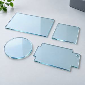
Custom domes, slide electrodes, patterned glass and transparent heaters
Explore application-specific ITO glass configurations for optical systems, laboratory equipment, displays and heating projects. Define conductivity, transmission and integration requirements together.
Explore ITO Products1. Custom Transparent Conductive Glass for OEM Projects
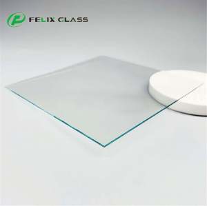
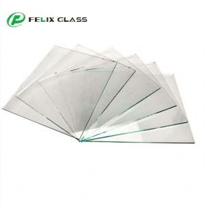
Dongguan Felix Glass Co., Ltd. supports custom ITO conductive glass projects for optical systems, laboratory instruments, displays and transparent heating. Specify the substrate, conductive area, optical requirements and electrical interfaces as one component.
From curved domes to patterned flat substrates, the right configuration depends on how the glass will be mounted, contacted and used. Send your drawing and application requirements for a project-specific manufacturing review and quotation.
2. Explore the ITO Product Range
| Product family | Typical project need | Start here |
|---|---|---|
| Custom ITO Conductive Glass Dome | Curved optical protection with a conductive layer | Dome requirements |
| Lab ITO Conductive Slide Electrodes | Transparent electrodes for laboratory research | Slide electrodes |
| Medical Grade ITO Conductive Glass | Components for defined medical-equipment requirements | Equipment requirements |
| Patterned ITO Conductive Glass | Defined tracks, pads and electrically isolated regions | Patterned electrodes |
| Custom ITO Heater Glass | Transparent heating for anti-fog windows and instruments | Heater glass |
| High Conductivity ITO Heater Glass for Medical Lab Heating | Heating projects with application-specific resistance and temperature targets | Laboratory heating |
The medical-laboratory heating and anti-fog heater products share the same electrical design principles, but require different thermal acceptance tests. Select by operating conditions rather than the product name alone.
3. Custom ITO Conductive Glass Dome
Curved ITO glass combines a shaped optical substrate with a transparent conductive surface. Define the dome diameter, height, wall thickness, curvature, flange and clear aperture, together with the face to be coated.
Curvature changes the coating geometry and the electrical current path. Agree on the locations used to measure sheet resistance and optical performance, plus contact placement and coating exclusions. For imaging systems, include angular transmission and image-quality requirements across the useful field.
4. Lab ITO Conductive Slide Electrodes
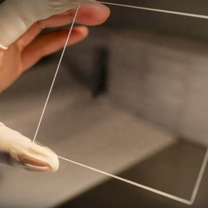
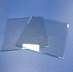
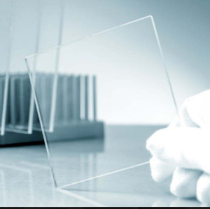
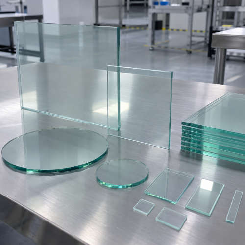
ITO-coated slides provide an optically accessible conductive surface for experimental setups. State the slide size, thickness, coated face, exposed electrode area and connection method, together with the wavelength band used for observation.
For electrochemical or solution-contact work, identify the electrolyte, voltage conditions, cleaning steps and exposure duration. Compatibility needs evaluation in the intended experiment. Bare conductive slides, patterned electrodes and heating slides should be specified separately because their test requirements differ.
5. Medical Grade ITO Conductive Glass
For medical-equipment projects, define the component function: an instrument window, display cover, heater or electrode. Include any patient-contact or fluid-contact conditions, cleaning processes and documentation requirements in the RFQ.
“Medical grade” is an application description that requires an agreed specification. It does not by itself establish sterility, biocompatibility, device approval or suitability for a particular clinical use. The finished component and the assembled equipment need the qualification required for their intended use.
6. Patterned ITO Conductive Glass
Patterned ITO defines conductive tracks, electrode arrays, contact pads and isolated zones. Submit dimensioned artwork and a controlled drawing showing the viewing side, coating side, datums, alignment marks and electrical connections.
Specify track width, gap, positional tolerance, active area and acceptable edge defects. Electrical acceptance should include continuity, path resistance and isolation between independent regions. Feature limits and the patterning route are confirmed after reviewing the design; a visible gap alone does not prove electrical isolation.
7. Custom ITO Heater Glass and Laboratory Heating
An ITO film can generate resistive heat when current flows between suitable contacts. Anti-fog windows require defined humidity and condensation conditions; laboratory heaters require defined temperature stability, sample loading and heat-transfer conditions.
Provide the supply voltage range, current or power limit, target temperature, warm-up time and uniformity area. Include airflow, mounting, ambient temperature and any liquid contact. High conductivity alone does not establish heating uniformity or temperature control.
At a stated operating resistance, DC electrical input follows P = V²/R. Temperature also depends on heat loss and the assembly. Confirm whether the scope includes only the glass, busbars, attached leads, sensors or control hardware. Anti-fog performance does not automatically establish de-icing capability.
8. Custom Specification Checklist
| Specification | Information to provide |
|---|---|
| Substrate | Glass type or approved grade; strengthening requirements |
| Mechanical geometry | Outline, thickness, tolerances, holes, edge finish and drawing revision |
| Coated area | Coated face, coverage, masking, edge exclusions and contact zones |
| Electrical performance | Sheet resistance and tolerance; mapping locations; terminal or track resistance |
| Optical performance | Transmission band and limits; angle; haze or imaging requirements |
| Pattern and contacts | Track layout, isolation, pads, busbars and connection scope |
| Thermal requirements | Power supply, ambient conditions, target temperature and uniformity |
| Qualification | Exposure tests, measurement methods, sampling and required reports |
Numerical limits are agreed for the specific substrate, geometry and process. Specify essential performance limits separately from preferred values so practical alternatives can be reviewed.
9. Substrate and Optical Performance
Candidate substrates include suitable soda-lime glass, borosilicate glass, optical glass and fused silica. Selection depends on the optical band, thermal conditions, geometry and downstream processing. Include any strengthening, printing or bonding steps before finalizing the coating sequence.
Specify transmission for the finished coated component. The substrate and conductive film both influence the result; visible clarity does not establish infrared performance. AR or protective layers can be reviewed as part of the full stack, with electrical contact areas kept accessible where required.
10. Sheet Resistance, Contacts and Current Paths
Sheet resistance describes the film in Ω/□. It is different from the resistance measured between terminals. For an ideal uniform rectangular film with full-width contacts on opposing edges, R = RₛL/W, where L is electrode spacing and W is the width perpendicular to current flow.
Curved shapes, small pads, narrow tracks and complex patterns require their own electrical assessment. Define the contact method and measurement temperature, and identify whether contact resistance is included. A sheet-resistance value alone cannot determine the power or voltage drop of the complete part.
11. From Drawing Review to Production
A custom project begins with the mechanical drawing, electrical layout and application conditions. The review establishes the substrate, coating coverage, contact design, inspection plan and any process-dependent changes needed for manufacture.
- Submit the drawing, artwork and functional targets.
- Agree on manufacturable geometry, supply scope and acceptance criteria.
- Order paid prototypes for dimensional, optical and electrical evaluation.
- Validate the part in the intended assembly and operating environment.
- Release the approved drawing revision and production inspection plan.
Prototype cost, tooling, minimum order quantity and lead time depend on the approved design and quantity. Confirm these items in the quotation before ordering.
12. Inspection, Handling and Packaging
An inspection plan may include dimensions, coated-area checks, sheet-resistance mapping, terminal resistance, electrical isolation and spectral transmission. Heater projects also need temperature testing under a defined mounting and power condition.
Agree on the sampling plan, report format and required traceability before production. Environmental tests should specify the exposure and the optical or electrical limits that must still be met afterward.
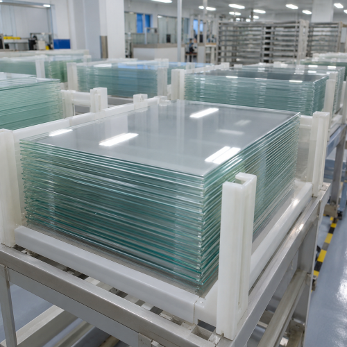
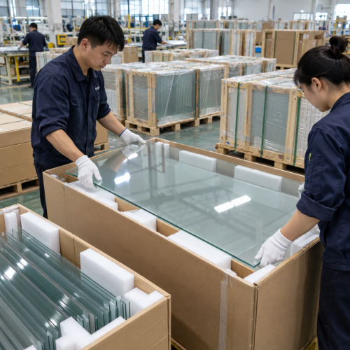
Packaging should separate parts and protect coated surfaces, edges and contacts from abrasion or movement. Identify the coated face and contact areas for assembly. Agree on cleaning and handling instructions for the supplied coating stack.
13. Prepare a Complete ITO Glass RFQ
Send a PDF drawing and editable geometry or artwork where available. Include the application, substrate, dimensions, coating side, active area, target sheet resistance, optical band and required contacts.
For heaters, add voltage, available power, target temperature, warm-up time, ambient conditions and mounting details. For electrodes, add continuity, isolation and solution-contact requirements. For domes, add curvature and the optical field used.
List prototype quantity, production quantity, expected repeat demand, delivery destination and required documentation. If a value is not yet fixed, explain the intended function so options can be reviewed without assuming a performance guarantee.
14. Frequently Asked Questions
Which ITO glass product should I choose?
Start with the geometry and function. Domes serve curved optical layouts; slides suit laboratory fixtures; patterned glass defines electrodes; heater glass requires a thermal and power specification.
Can dimensions and coating areas be customized?
Submit the drawing, coated face and exclusion zones. Feasibility, tolerances and production requirements are confirmed during review.
Is lower sheet resistance always better?
No. It affects current flow and power and must be evaluated with optical performance, geometry and contacts.
Can ITO glass combine conductivity and AR performance?
A compatible layer stack can be reviewed. Specify the optical band and retain access to the conductive layer at the required contacts.
Does medical grade mean the component is certified for my device?
No. Define the intended use, component acceptance criteria and required documentation. Device-specific qualification remains necessary.
Are busbars, leads and controllers included?
Only if included in the quotation and agreed supply scope. Identify each required item in the RFQ.
Can I request samples before production?
Paid prototypes can be quoted for evaluation. Cost, quantity and lead time depend on the design and processing scope.
What information is needed for an accurate quotation?
Provide the drawing, substrate, electrical and optical targets, operating conditions, contacts, quantities and inspection requirements.
15. Request a Custom ITO Conductive Glass Quote
Discuss your dome, electrode, patterned glass or transparent heater project with Felix Glass. Send your drawing and the performance targets that matter in your assembly for a technical review and quotation.
Dongguan Felix Glass Co., Ltd.
Email: james@felixglass.com
Phone: +86-18565032888